49
Note
:
At the end of the process the initial configuration
steps will continue. If the language string transfer process
from USB to panel fails, a fault page is displayed and the
default Italian language is restored.
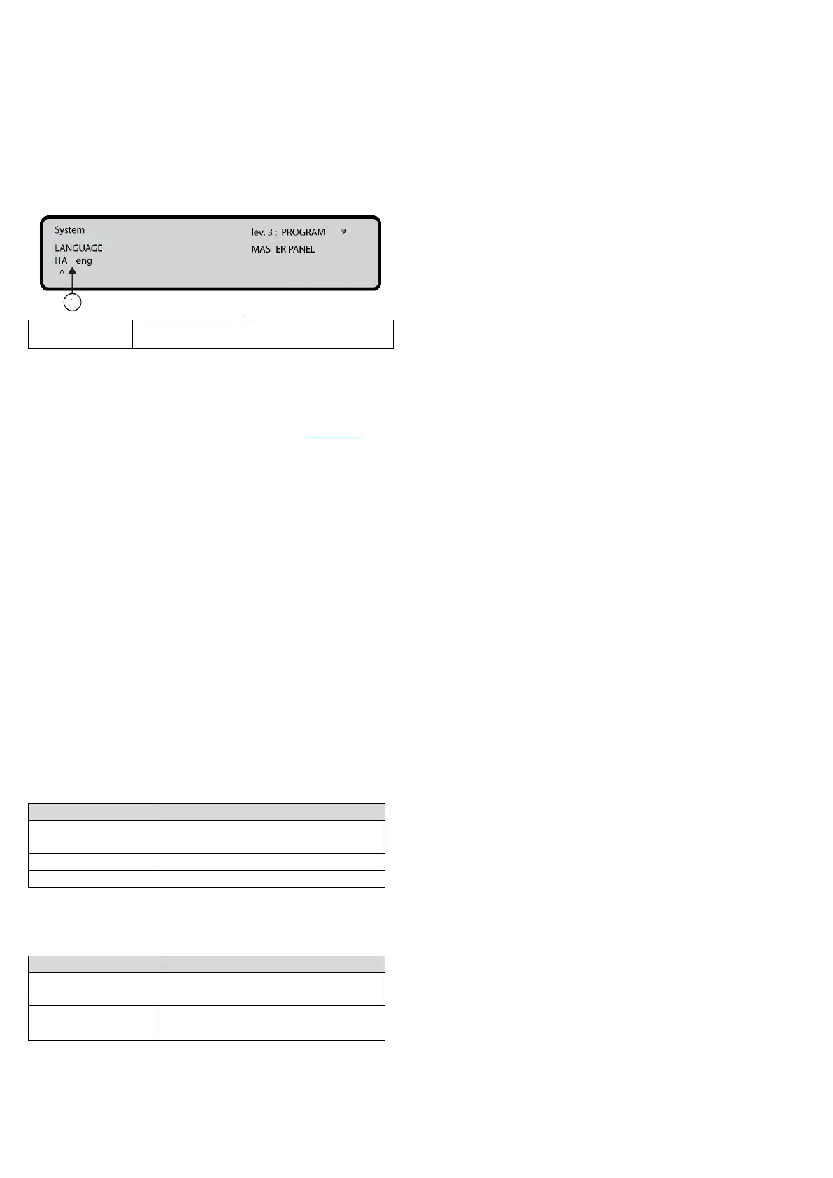
Figure 35: Select the language of the system
8 Key – System
Use the System option in the PROGRAM screen to activate
the system language selection screen. See Figure 24, 0.
Note: Other languages can be loaded from the software.
After selecting the language, program the following options:
-PANEL ID
-PANEL TYPE (FC503 or FC506)
-BATTERY TYPE (17Ah or 38Ah)
-DAY/NIGHT MODE or AUTO
-DELAY TO ALARM TIME.
-COPY ON ZONE?
-MONST. OUTPUT TIME
-ENABLE SCREEN SAVER
-2 Wire Loops
In this phase the keypad and keys have the following
functions:
Alphanumeric keypad
No function is related to the alphanumeric keypad.
Cursor keys
Table 53: Cursor key functions in system
Use to select the next option
Use to select the previous option
ESC and ENTER keys
Table 54: ESC and ENTER key function in system
Use to cancel the operation or
return to the MAIN screen
Use to accept the selection
Panel ID
Enter up to 4 digits to identify the configuration file
system. Ensure you can distinguish it from other
configuration files.
-PANEL TYPE (FC503 or FC506)
-BATTERY TYPE (17Ah or 38Ah)
Day / Night / Auto
The display for programming Day, Night, or Auto mode will
be shown. If Auto mode is chosen, set the transition time
from one mode to another. See the LED Day/Night mode
LED change status.
Delay to alarm time
Enter the Delay to alarm time in minutes. The maximum
time is 9 minutes. The total time for Delay to alarm time and
investigation time should not exceed 10 minutes.
Copy on zone?
Select the YES option using the cursor keys to copy the
same Delay to alarm time in all the zones.
MONST. OUTPUT TIME
Enter the period of time that the outputs, with the
monostable option set, will stay active once triggered. The
value ranges from 1 minute to 30 minutes with a default
value of 3 minutes. The mono-stable output time is valid
for the entire system.
ENABLE SCREEN SAVER
Select the YES option using the cursor keys to display the
customizable front screen. If NO is selected, it is
permanently removed.
2 Wire Loops
Each loop may be individually set to work in 2 wires mode
(multiple selection). When the 2 wires mode is selected, it
is possible to connect devices on both the left and right
sides of the loops (2 spurs). This allows for the connection
of up to 6 spurs to the panel, mimicking a 6 zones
conventional panel.
Notes:
In all descriptions of the events, the devices are
indicated as belonging to a loop. In the case of open
loops, it is not possible to distinguish between the left
and right side. Loop concept, therefore, will not be
meaningful by definition, and localization will be
performed using zones as in the case of conventional
panels.
If devices are addressed by the service tool, set them in
the 6 zones which correspond to the 6 spurs by
assigning the correct zone to each device using the PC
console or a control panel LCD.
If devices are not addressed, a mapping procedure is
performed to locate each device and assign the correct
zone to it.