12
ON indicates that the control panel is operating in day mode.
OFF indicates that the control panel is operating in night mode.
ON indicates that the corresponding software zones are in Alarm status *.
Note: * indicates that the zone outside the 1- 8 range does not have a related
LED, its alarm status is displayed only by the LCD.
Blinking indicates that the corresponding software zones are in Delay to Alarm
status.
ON indicates that the control panel is at least at level 2 so the
SILENCE/RESOUND SOUNDERS, RESET and INVESTIGATION DELAY keys
are enabled.
Note: * the zone outside the 1 to 8 range does not have a related LED, its alarm status is displayed
only by the LCD, ** buzzer SYSTEM FAULT pattern, *** buzzer FAULT pattern.
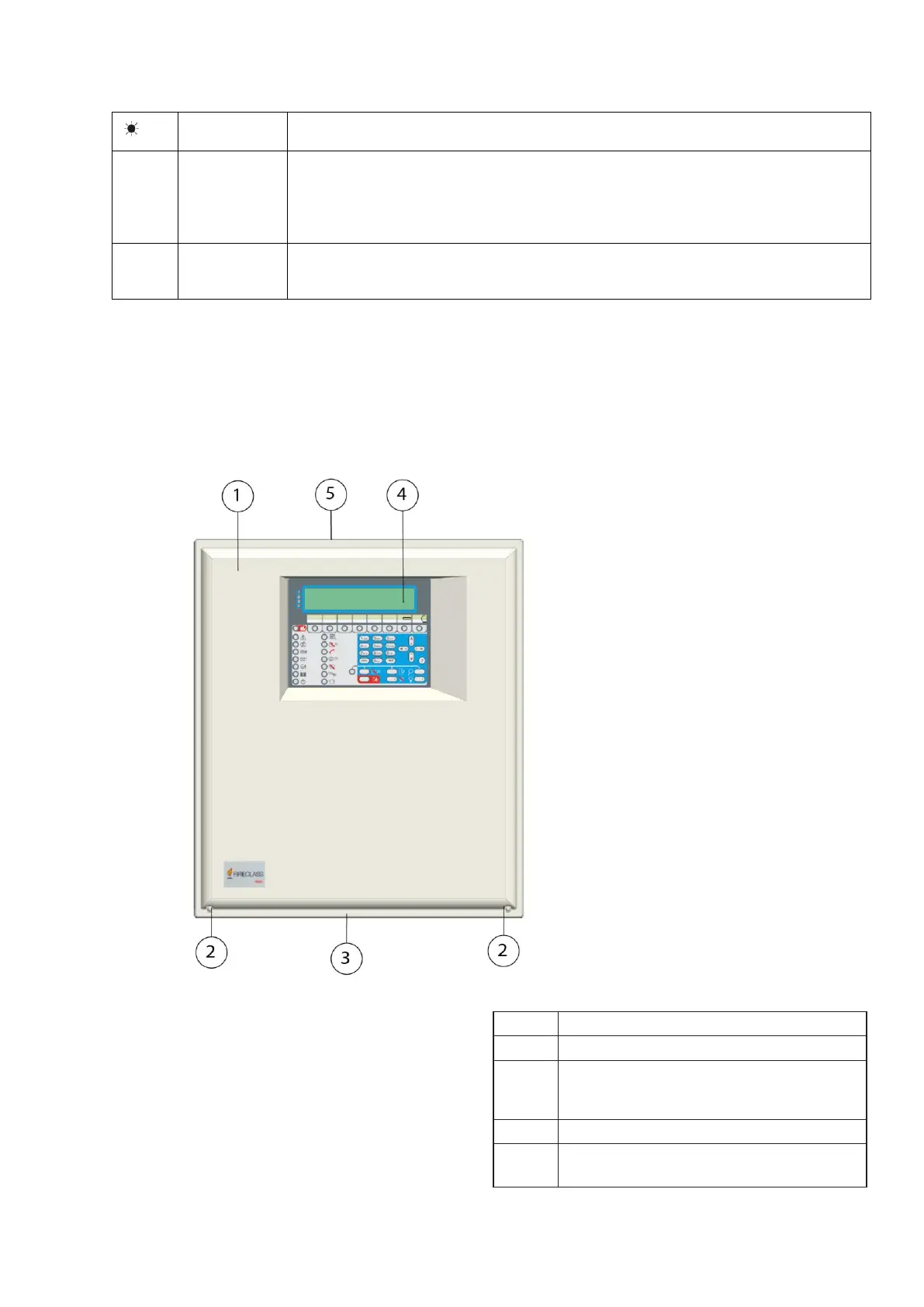
Parts identification
Figure 1: FC503 and FC506 Parts: external view
Description of parts
This section describes the components of the FC503 and
FC506 control panels.
Unless otherwise stated, the numbers in boldface in this
manual refer to the tables and diagrams in this section.
Screws (2) to close the cover on panel
Knockout for connection FC503, FC506
panel with FC500BX battery cabinet
(accessory item) (1)
Knockouts for cables ducted externally
(18)