11
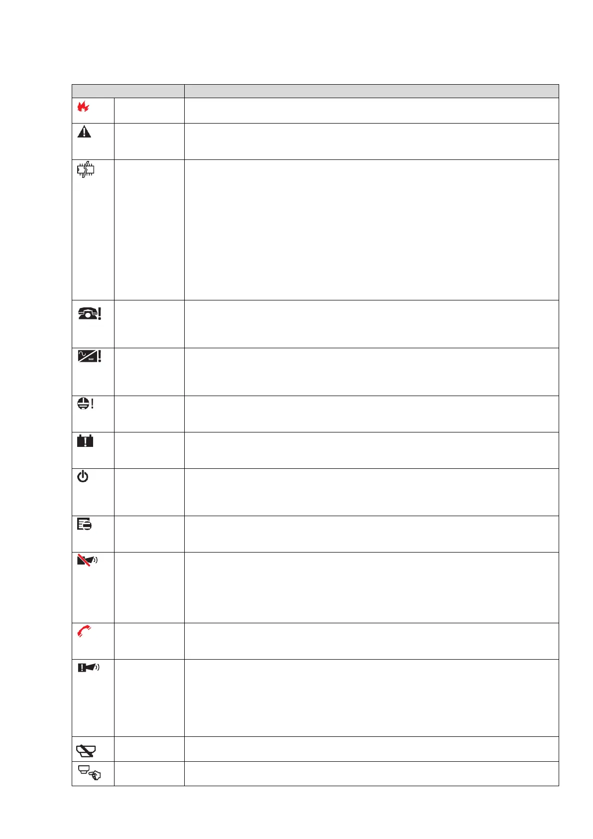
Table 5: Description of the status LEDs.
ON indicates the alarm status. In the event of an alarm, the control panel activates
the unbypassed alarm outputs.
ON indicates the presence of a fault. The following LEDs or the screen display
indicates the type of fault. OFF indicates no fault.
ON ** indicates a blocked control panel and *** indicates the control panel restart.
IMPORTANT: Maintenance required.
Blinking *** indicates that the data panel programming is corrupted.
Note: When the control panel is switched on for the first time, this LED blinks until
a reset has been performed.
Note: ** indicates the buzzer system fault pattern; *** indicates the buzzer fault
pattern.
Note: The System fault LED latches if one of the below conditions occurs:
The system resets itself (watchdog reset) when any internal logical fault
occurs.
System is powered ON after a complete panel shut down.
FIRE
SIGNAL
FAULT
(Amber)
ON indicates that the communicator is disabled.
Blinking indicates that the communicator is faulty.
POWER
SUPPLY
FAULT
(Amber)
ON indicates a mains failure (230 V).
Blinking indicates a Switching Power supply fault.
During this condition, the control panel is powered by the batteries.
ON indicates a voltage leakage to Earth.
IMPORTANT: Check wiring insulation.
ON indicates that the batteries are empty or faulty. If this condition persists, the
batteries are unable to function as intended in the event of a blackout.
IMPORTANT: New batteries are required.
ON indicates that the panel is supplied with power. OFF indicates a mains failure
whereby both mains and battery power is lost (the battery disconnect threshold is
19.2 V). Power must be restored before the batteries reach the disconnect
threshold.
ON indicates that there is hidden information with lower priority.
View List shows the hidden information.
OFF indicates no hidden information is available.
SOUNDERS
SILENCED
(Amber)
ON indicates that the silenceable outputs and loop device have been forced into
standby by means of the SILENCE/ RESOUND SOUNDERS key. In day mode,
the silence status remains until the SILENCE/RESOUND SOUNDER key is
pressed again. In night mode, the silence status remains until the night mode
silence time expires or until the system detects a new alarm or a new trouble
condition.
ON indicates that the transmission was successful.
Blinking indicates that the transmission is in progress. On the control panel
screen, the connection type, such as PSTN, GSM, or LAN network, is displayed.
SOUNDERS
FAULTS/DIS
(Amber)
ON indicates that the output is disabled or outputs configured to "act as SC1" are
disabled.
Blinking indicates that the SC1 is in fault or outputs configured to "act as SC1"
are in fault.
OFF indicates that all the main sounder outputs (EN54-1, TYPE "C" outputs)
function properly.
ON indicates the disabled status of any bypassable entity.
ON indicates the test conditions on at least one zone.