28
Installing the FC500IP board
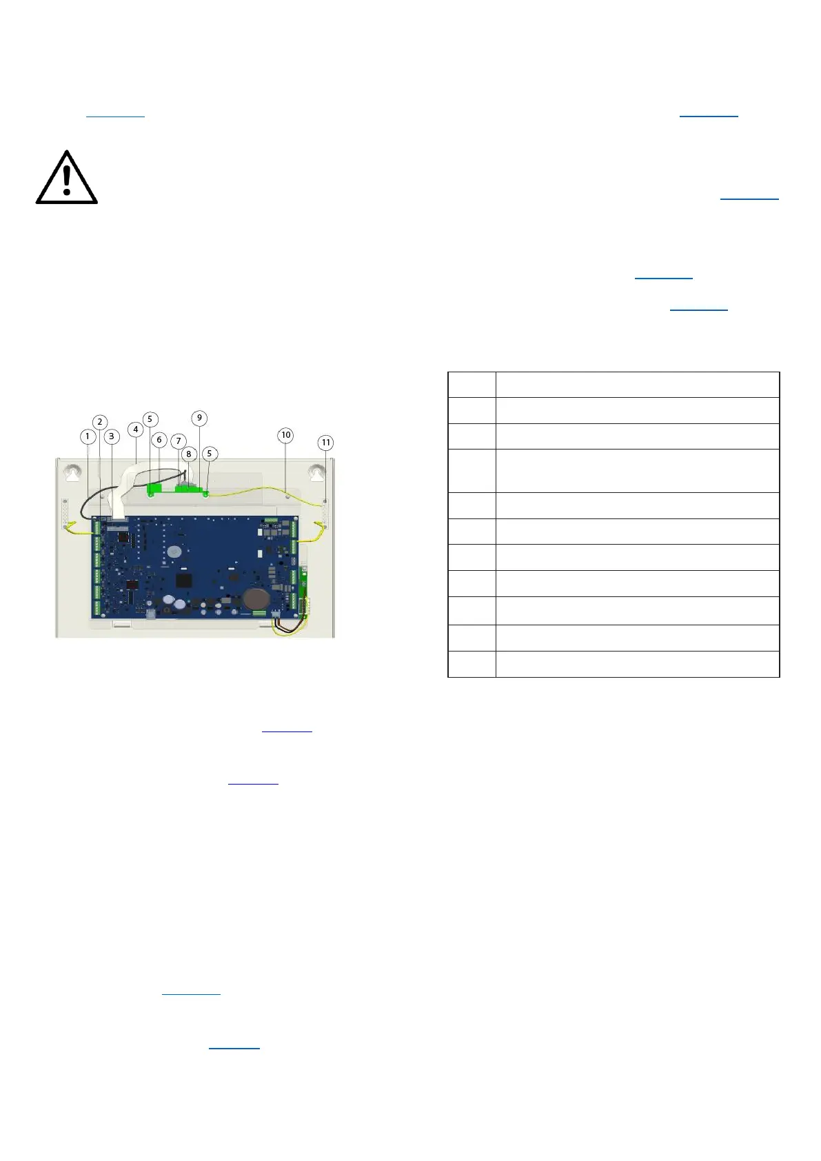
Install the IP module into the base of the control panel, as
shown in Figure 15. Follow these instructions to install the
FC500IP board.
CAUTION
Before installing the FC500IP Module,
disconnect the control panel from its
power supply, the mains, and the
batteries.
You must connect the IP module to the
earth of the electricity supply system.
You must insert the earth cable (item
10) between the fixing bracket of the
module, the screw (item 5) and the
earth terminal (item 11).
Figure 15: FC503 connection with the FC500IP
Do not remove the wiring already present on the screw
(item 11).
1. Open the control panel by unscrewing the two
screws, then lift the cover from the bottom to
separate it from the chassis. See Figure 1, item 2.
2. Remove the fastening screw between the control
board and the chassis. See Figure 2, item 6.
3. Unlock the control board support and user
interface using a flat screwdriver.
4. Lift the control board and user interface display
from the base.
5. Insert the IP module below the chassis and align
the mounting holes given.
6. Put the IP module screws through the holes on
the chassis. See Figure 15, item 5.
7. Assemble the control board again in place with the
help of four screws. See Figure 2, item 6.
8. Re-fit the control board and display and secure
the screw.
9. Connect the IP module connector (Figure 15, item
8) to the control panel connector (item 3) using the
supplied flat cable (item 4).
10. If you only need to manage the control panel through
the IP, connect the IP module connector (Figure 15,
item 7) to the control panel connector (item 2) using
the supplied PC link cable (item 1).
11. Connect the cable (item 10) between the screws
(item 5) and (item 11). See Figure 15.
12. Connect the Ethernet connector (Figure 15, item 6)
to the LAN using an Ethernet cable.
Note: Use a category 5 or greater Ethernet cable,
STP, or FTP.
13. Reconnect the control panel to the power supply.
14. Program the IP Module as described in the section
PC Programming.
Serial port RS 232 (PC LINK)
Module IP (FC500IP) connector
Flat cable for the connection with
FC500IP
Cable for earth wiring of the FC500IP