71
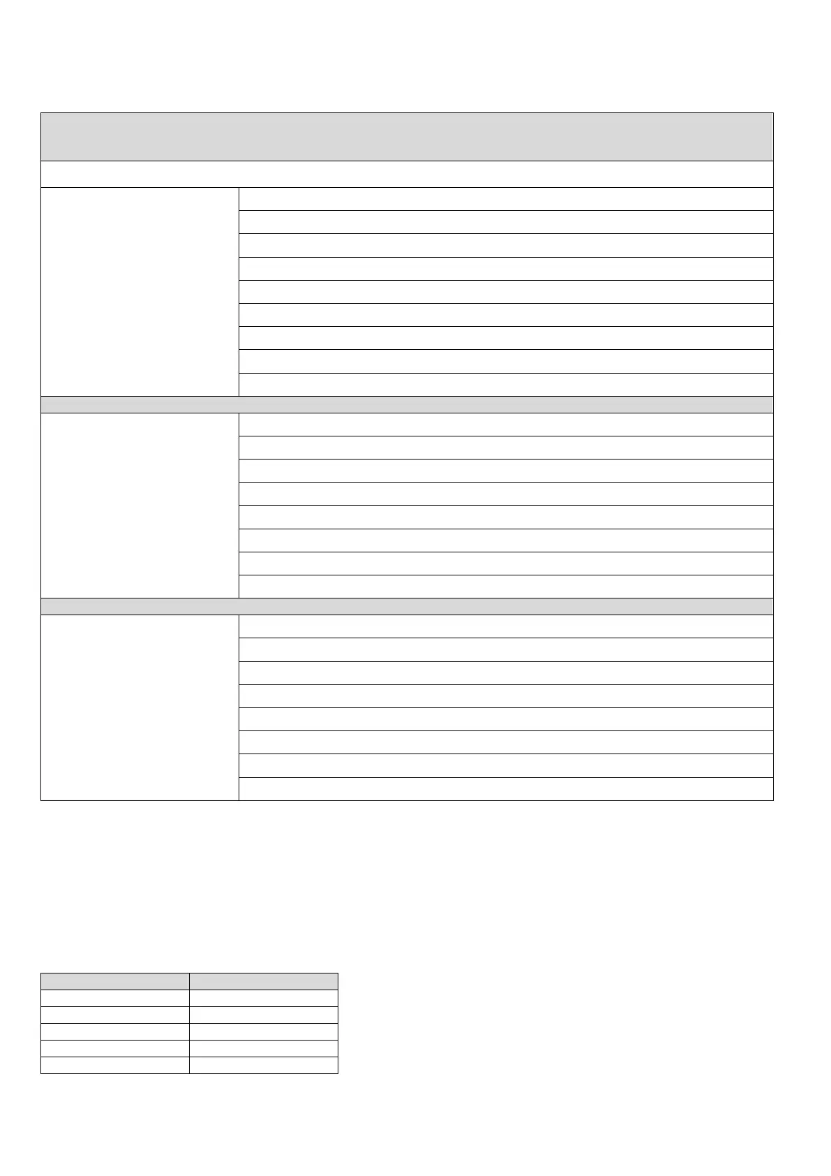
Table 66: Current distribution of FC503 control panel
Switching Power Supply BAQ140T24 (Imax = 5.5 A)
IBattery_Charge_80%_24H = (12*0.8)/24 = 400 mA
IFor_panel = 5500 - 400 = 5100 mA
IMain_Board_Electronics = 250 mA
ITotal_Loops_1_2_3 (*) = 800 mA @40V (1300 mA @27V)
ITotal_Outputs (***) = 3300 mA
IBattery_Charge_80%_24H = (12*0.8)/24 = 400 mA
IBattery_Charge_80%_24H = (17*0.8)/24 = 566.66 mA -> 600 mA
IFor_panel = 5500 - 600 = 4900 mA
IMain_Board_Electronics = 250 mA
ITotal_Loops_1_2_3 (*) = 800 mA @40V (1300 mA @27V)
ITotal_Outputs (***) = 3100 mA
IBattery_Charge_80%_24H = (38*0.8)/24 = 1266.66 mA -> 1500 mA
IFor_panel = 5500 - 1500 = 4000 mA
IMain_Board_Electronics = 250 mA
ITotal_Loops_1_2_3 (*) = 800 mA @40V (1300 mA @27V)
ITotal_Outputs (***) = 2200 mA
Notes:
(*):ITotal_Loops_1_2_3 is the sum of currents absorbed on Loops 1, 2, 3
(**):ITotal_Loops_4_5_6 is the sum of currents absorbed on Loops 4, 5, 6
(***):ITotal_Outputs is the sum of the currents drawn by the terminals SC1, SC2, 24A, 24R, 24V-RS485.
(****): If the FC500IP module is not be used then the relative amount of current (100 mA) can be drawn from the
SC1, SC2, 24A, 24R, 24V-RS485 terminals.
Table 67: Max withdrawable current for FC503 and FC506 control panels