Instruction Manual
D103412X012
Detailed Setup—PID Function Block
July 2013
137
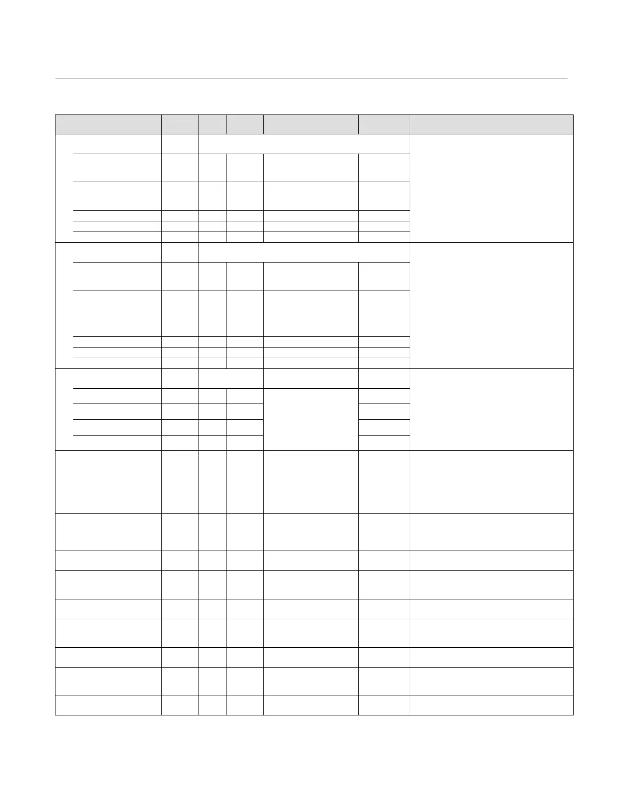
Table 4‐32. PID Function Block System Parameters Definitions (Continued)
DescriptionInitial ValueRange
Block
Mode
RO /
RW
Index
Number
Label
PARAMETER_NAME
Update Event
UPDATE_EVT
43
Data Type: DS‐73
This alert is generated by any changes to the static
data.
UNACKNOWLEDGED 43.1 RW N/A
0=Undefined
1=Acknowledged
2=
Unacknowledged
0
UPDATE_STATE 43.2 RO N/A
0=Undefined
1=Update reported
2=Update not reported
0
TIME_STAMP 43.3 RO N/A 0
STATIC_REVISION 43.4 RO N/A 0
RELATIVE_INDEX 43.5 RO N/A 0
Block Alarm
BLOCK_ALM
44
Data Type: DS‐72
The block alarm is used for all configuration,
hardware, connection failure, or system problems
in the block. The cause of the alarm will be set in
the subcode.
VALUE Data Type: Unsigned8
UNACKNOWLEDGED 44.1 RW N/A
0=Undefined
1=Acknowledged
2=
Unacknowledged
0
ALARM_STATE 44.2 RO N/A
0=Undefined
1=Clear‐reported
2=Clear‐not reported
3=Active reported
4=Active not reported
0
TIME_STAMP 44.3 RO N/A 0
SUBCODE 44.4 RO N/A 0
VALUE 44.5 RO N/A 0
Alarm Summary
ALARM_SUM
45
Data Type: DS‐74
Current alert status, unacknowledged states,
unreported states, and disabled states of the
alarms associated with the function block.
CURRENT 45.1 RO ALL
1: High High Alarm
2: High Alarm
3: Low Low Alarm
4: Low Alarm
5: Deviation High Alarm
6: Deviation Low Alarm
7: Block Alarm
Dynamic
UNACKNOWLEDGED 45.2 RO ALL
UNREPORTED 45.3 RO ALL
DISABLED 45.4 RW ALL
Acknowledge Option
ACK_OPTION
46 N/A
1: High High Alarm
2: High Alarm
3: Low Low Alarm
4: Low Alarm
5: Deviation High Alarm
6: Deviation Low Alarm
7: Block Alarm
All bits: 0
Data Type: Bit String
0=Disable
1=Enable
Used to set auto acknowledgment of alarms.
Alarm Hysteresis
ALARM_HYS
47 ALL 0 to 50% 0.50%
Data Type: Float
The amount the alarm value must return to within
the alarm limit before the associated active alarm
condition clears.
High High Priority
HI_HI_PRI
48 ALL 0 to 15 0
Data Type: Unsigned8
The priority of the HI HI Alarm.
High High Limit
HI_HI_LIM
49 ALL PV_SCALE, or +INF +INF
Data Type: Float
The setting for the alarm limit used to detect the
HI HI alarm condition.
High Priority
HI_PRI
50 ALL 0 to 15 0
Data Type: Unsigned8
The priority of the HI alarm.
High Limit
HI_LIM
51 ALL PV_SCALE, or +INF +INF
Data Type: Float
The setting for the alarm limit used to detect the
HI alarm condition.
Low Priority
LO_PRI
52 ALL 0 to 15 0
Data Type: Unsigned8
The priority of the LO alarm.
Low Limit
LO_LIM
53 ALL PV_SCALE, or -INF -INF
Data Type: Float
The setting for the alarm limit used to detect the
LO alarm condition.
Low Low Priority
LO_LO_PRI
54 ALL 0 to 15 0
Data Type: Unsigned8
The priority of the LO LO alarm.
-Continued-
 Loading...


