Instruction Manual
D103412X012
Detailed Setup—OS Function Block
July 2013
165
to OUT_2, or goes to Y
11
. If LOCKVAL is true, OUT_1 remains at its ending value when X is greater than X
12
. If LOCKVAL
is false, then OUT_1 goes to Y
11
when X is greater than X
12
.
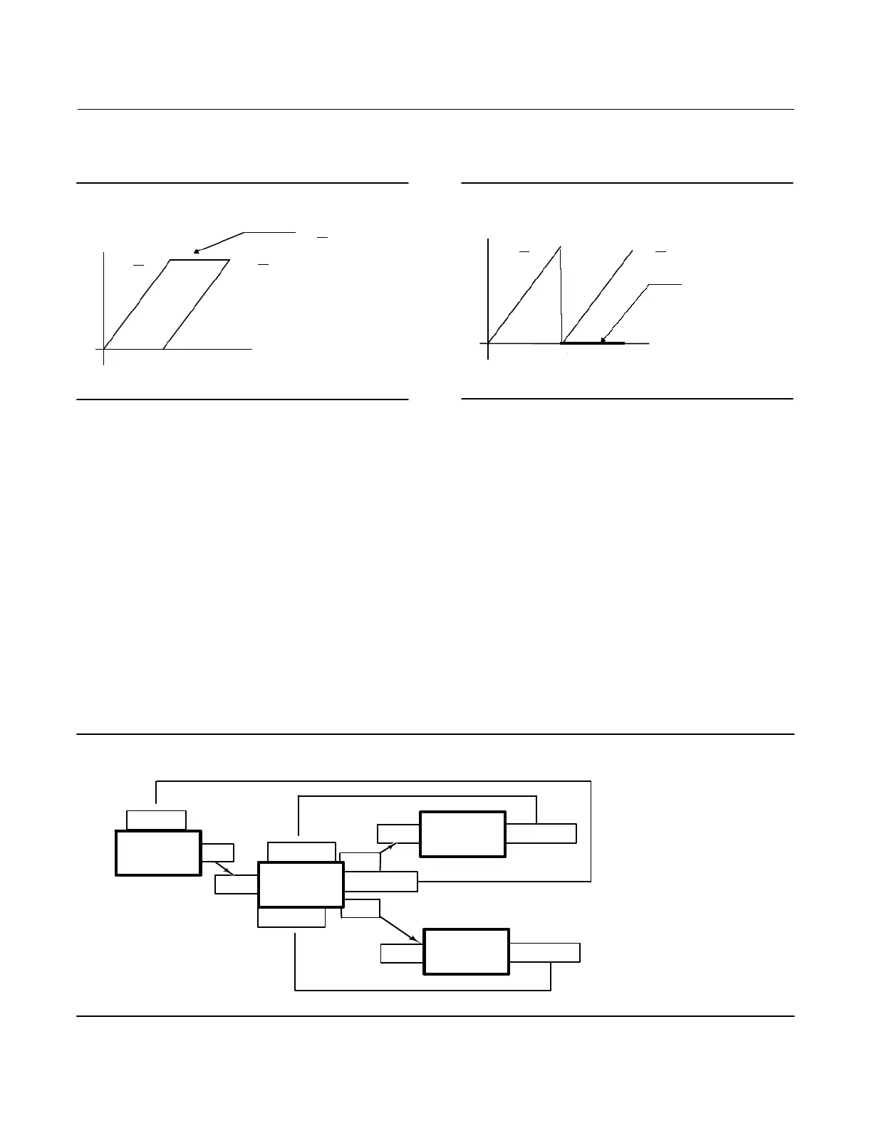
Figure 4‐20. OUT with LOCKVAL True
0%
SP
OUT
1
OUT
2
OUT
1 remains at
end point when
OUT_2 is non‐zero
50%
100%
Figure 4‐21. OUT with LOCKVAL False
OUT 1 OUT 2
0%
SP
50%
100%
OUT_1 goes to zero
OUT_2 becomes
Some hysteresis in the switching point may be required because the output may change by a full stroke of the valve.
HYSTVAL [12] contains the amount of hysteresis. If X < = X12-HYSTVAL, OUT_1 may be determined by the calculated
y value. If X12-HYSTVAL < X < X12 and X has not reached X12 since it was less than X12-HYSTVAL, OUT_1 may be
determined by the calculated y value. If X12-HYSTVAL < X < X12 and X has reached X12 since it was less than
X12-HYSTVAL, OUT_1 may be determined by the LOCKVAL setting. If X12 < X, OUT_1 may be determined by the
LOCKVAL setting.
Initialization and Back Calculation Requirements
Refer to figure 4‐22, Output Splitter Configuration, where:
PID1 = Upstream driving controller or function block.
Splitter = Split range function block being described.
AO = Receiver of OUT_1 for 0-50% range of SP
PID2 = Receiver of OUT_2 for 50-100% range of SP
Figure 4‐22. Output Splitter Configuration
AO
PID2
PID1
Splitter
BK_CAL_IN
CAS‐IN
OUT
BK_CAL_OUT
BK_CAL_IN2
BK_CAL_IN1
BK_CAL_OUT
BK_CAL_OUT
CAS‐IN
CAS‐IN
OUT2
OUT1
 Loading...


