HyPower-Geko Electrical connection
FläktGroup DC-2014-0022-GB 2018-05/R5 • Subject to modifications 57
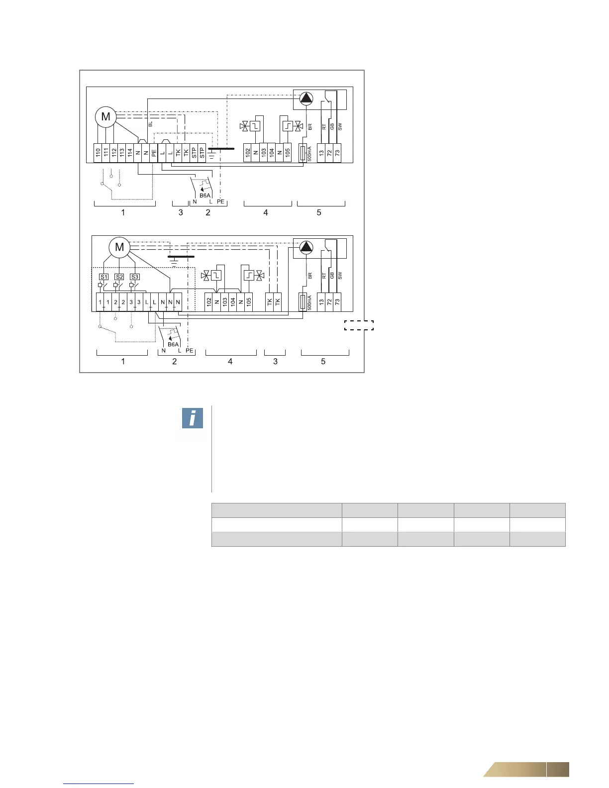
Pos. 1: Fan control (terminal diagram depending
on selected rotational speed combina-
tion, see wiring diagram in the electric
switch cabinet).
Pos. 2: Power supply 230 V AC;
fusing by others max. 6 A
Pos. 3: External terminals for
thermal contacts
Pos. 4: Connecting terminals for valves
Pos. 5: Connecting terminals for condensate
pump fault (optional)
relay PCB
Only terminals for wiring control and steering
system are presented.
Depending on the unit configuration, the
number of terminals varies.
• Connect multiple HyPower-Geko units in
accordance with the wiring diagram.
Fig. 6-3: Connection termial block/relay PCB
User instructions!
Before commencing connections, check that the order code of the unit's electrical
equipment matches the wiring diagram. Only one fan speed stage may be activated
simultaneously! If the fan-coil unit is to be connected to an on-site control system,
in the event of an on-site condensate pump fault, it must be ensured that the fan
shuts down once the alarm contact is triggered and the cooling valve is closed.
Refer to the unit connection diagram for connecting terminals with error messages.
 Loading...

