Electrical connection HyPower-Geko
58 FläktGroup DC-2014-0022-GB 2018-05/R5 • Subject to modifications
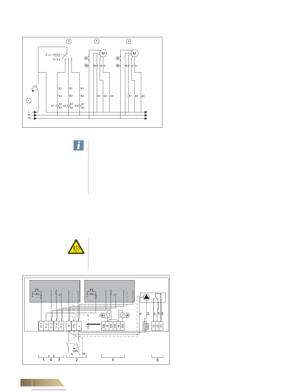
Connecting multiple HyPower-Geko units without FG-relay PCB
6.4.2 Connection of HyPower-Geko with EC motors
EC motors require 230 V AC 50 Hz supply voltage. 0-10 V DC or PWM signal is
required for for RPM regulation.
Multiple EC motors can be wired in parallel with regard to supply voltage and control
signal..
Pos. 1: Power supply 230 V AC / 50 Hz,
fusing by others max. B 6 A
Pos. 2: Speed selection switch
Pos. 3: HyPower-Geko Nr. 1, 3-speed fan
Pos. 4: HyPower-Geko Nr. 2, 3-speed fan
• Connect multiple HyPower-Geko units in
accordance with the wiring diagram.
• For 5-speed regulation an additional relay
is required. Use the given wiring diagram to
connect 3-speed fans.
Fig. 6-4: Connecting multiple HyPower-Geko units without FG-relay PCB
User instructions!
Multiple HyPower-Geko units without a FG-relay circuit board can be equipped and
combined with an external controller according to Fig. 6-4. Cut-off relays must be
provided by others (K1 - K3).
HyPower-Geko units with a FG-relay circuit board are prepared for parallel opera-
tion. Only one fan speed stage may be activated simultaneously!
A minimum switch pause of 0.1 sec. must be maintained between changing speeds!
According to the relevant regulations, an all-pole isolating device must be provided
by others on-site!
Damage to the unit!
If multiple motors are installed in one unit, alarm signals must be tapped off for each
motor separately if a control system provided on-site is used. The error signal is
ground-referenced and a serial interconnection of multiple outputs can cause motor
damage. An overload of malfunction-report outputs can also cause motor damage.
Pos. 1: Alarm signals (not floating; max.
stress tolerance of 10 mA), terminals
11.1 = EC motor 1,
11.2 = EC motor 2 (only certain sizes,
refer to Tab. 6-5)
Pos. 2: Power supply 230 V AC; on-site fus-
ing max. 6 A
Pos. 3: Control signal 0-10 V DC 1 / PWM
(max. consumption of 0.1mA)
Pos. 4: Output voltage 10V DC
(max. loading capacity of 1mA)
Pos. 5: Connecting terminals for valves
Pos. 6: Connecting terminals for condensate
pump fault (optional)
• Connect multiple HyPower-Geko units
in accordance with the wiring diagram.
Fig. 6-5: Connecting HyPower-Geko with EC motors
 Loading...

