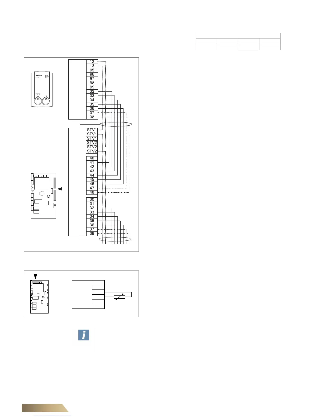
Connecting control panel – unit - other slave units
Control panel MATRIX OP21 can only be connected to units
equipped with MATRIX 2000.A maximum of 16 units can be
connected to OP21.
• Connect control cables in accordance with the wiring
diagram.
– Control cable: see top note on Seite 63.
– With valve actuators, the connections between control pan-
el and air-treatment units should be carried out using 37/47
and 38/48 terminals. (-·-·-)
– If connecting an external room, return-air or inlet-air sensor,
the connection can be completed using terminals 12 and 13
of the control panel or support terminals STV1 / STV2 if
these are not occupied. When using support terminals, 2
additional cores for terminals 12 and 13 of the control panel
should be provided. (-----)
– In units with a return or inlet sensor, 2 additional cores for
terminals 12 and 13 of the control panel must be installed.
An external room sensor cannot be connected with this con-
figuration. The wiring of the sensor is completed via support
terminals STV1/STV2. (-----)
Fig. 6-10: Connecting control panel – units
Connecting external room-temperature sensor or return-
air sensor (optional) or inlet sensor
• Connect the sensors in accordance with the wiring diagram.
– Sensor lines as control cables: refer to top note on Seite 63.
Fig. 6-11: Connecting sensor
User instructions!
Likewise only one external room sensor or one return-air sensor or only one inlet
sensor per unit group per control panel can be connected.
 Loading...

