Electrical connection HyPower-Geko
68 FläktGroup DC-2014-0022-GB 2018-05/R5 • Subject to modifications
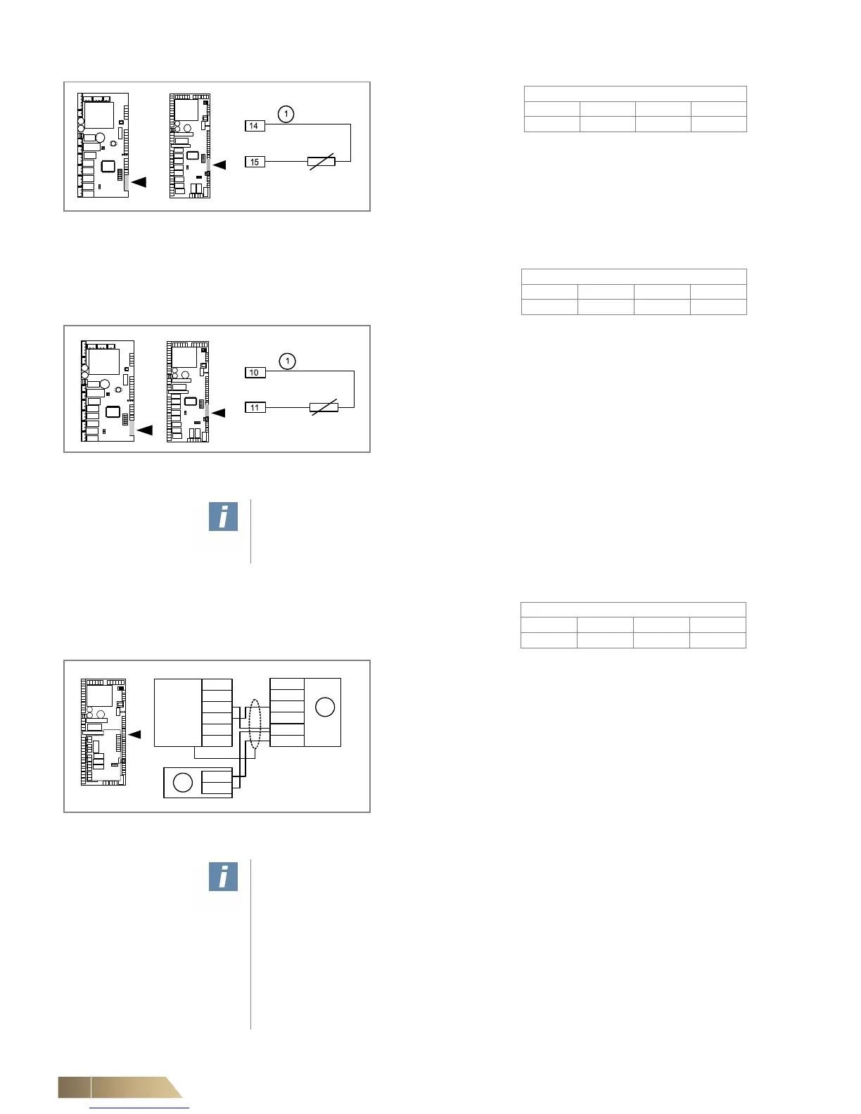
6.7.7 Connecting supply-air sensor (for subsequent retrofitting)
6.7.8 Connecting air quality sensor
Pos. 1: Con-
necting cable (refer to notice on Seite 63)
• Connect the room or return-air sensor according to the wiring
diagram.
Fig. 6-20: Connecting room sensor/return-air sensor
Pos. 1: Connecting cable (refer to notice on Seite 63)
• Connect the supply-air sensor according to the wiring
diagram.
Fig. 6-21: Connecting supply-air sensor
User instructions!
Connect the shielding of sensor lines with the cable shield grounding clamp to a
large ground area!
For connecting cable refer to notice on Seite 63
Pos. 1: Air quality sensor
Pos. 2: Power supply unit (by others)
• Connect air quality sensor in accordance with the wiring
diagram.
Fig. 6-22: Connecting air quality sensor
User instructions!
Illustrated connecting terminals of the sensors relate to type 903WRF04CO2V. The
sensor requires supply voltage of 24 V AC/DC and its power consumption amounts
to 3 W / 6 VA.
Measuring range: 0..2000 ppm. Output signal: 0-10 V.
Power supply unit is to be provided by others. If other sensors are used, refer to the
technical data for current consumption and power supply. The sensor input of the
controller is adjusted by the factory to a range of 2000 ppm. If other sensors are
used, additional adjustment may be required. Use the MATRIX.PC service tool to
perform such tasks.
 Loading...

