Electrical connection HyPower-Geko
78 FläktGroup DC-2014-0022-GB 2018-05/R5 • Subject to modifications
6.10.2 Operating mode only heating – only cooling – heating or cooling (2-pipe system)
6.10.3 Operating mode Only Heating (2-pipe system)
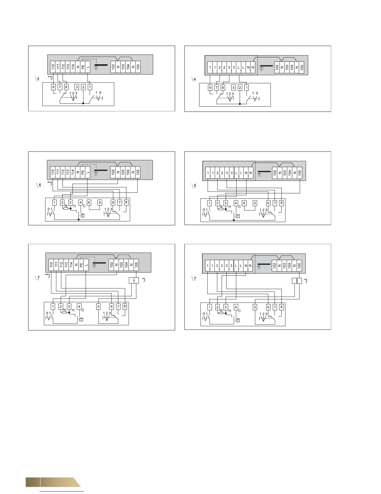
*) Intermediate terminals must be set by others on-site.
**) Fan control (terminal diagram depending on selected rotational speed combination, see wiring diagram in the electric switch cabinet.
Fig. 6-34: Manual fan control
(unit with terminal strip)
Fig. 6-35: Manual fan control
(unit with relay PCB)
Fig. 6-36: Fan continuous mode and valve control
(unit with terminal strip)
Fig. 6-37: Fan continuous mode and valve control
(unit with relay PCB)
Fig. 6-38: Fan and valve control
(unit with terminal strip)
Fig. 6-39: Fan and valve control
(unit with relay PCB)
 Loading...

