TemplateA4_v20130506
10
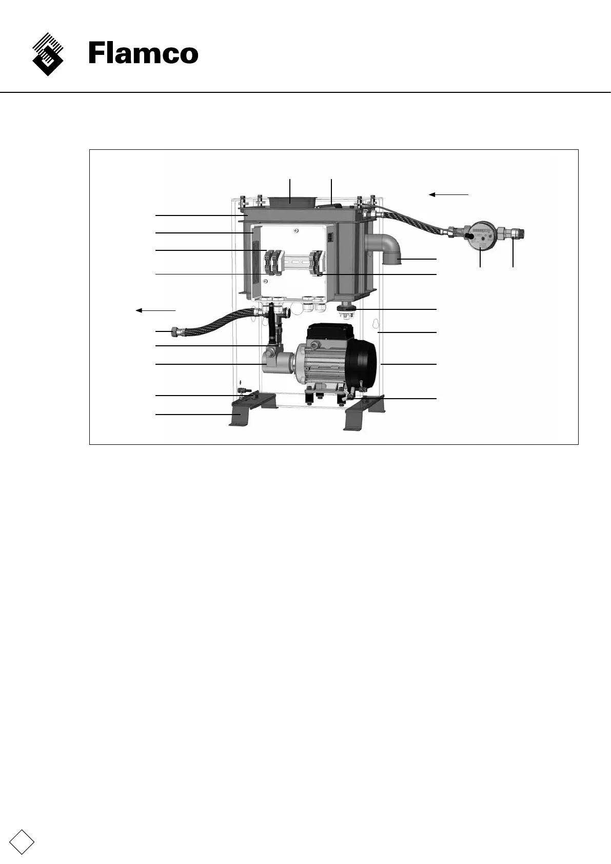
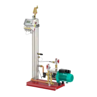
2.4 Components, equipment
5 3
Feed
System
2 1
6
10
17
18
11
4
15
9
13
12
19
8
14
7
16
1. Non-return valve
2. Watermeterwithpulseoutput(IWZ/pwm)
3. Floatvalveforllingwithsystemseparation
4. Break tank
5. Cover for housing access to the break tank
6. Breaktankoverowconnection
7. Housing(onlyedgesportrayed;earthconnection
markedwithalabelonthefrontside)
8. Pressure switch for the pump's dry run protection
9. Pump
10. Pressure hose – connection to the system
11. Terminal box with connection contacts to the top hat rail
(andtransparentcover)
12. Feet as optional equipment
13. Threaded connections for Pos. 12
14. Removable housing side panel
(onlyedgesportrayed)
15.Non-returnvalve(preventsreverseowoutofthesystem
intothebreaktank).
16.Externalprotectiveearth(PE)conductorconnection
17. Terminal block for connecting the pressure switch
andfortheelectricalconnectiontotheSPC(tobeprovided
bythecustomer)
18. Terminal block for connecting the pulse water meter
andforelectricalconnectiontotheSPC(tobeprovidedby
thecustomer)
19. Terminal block for connecting the pump
andforelectricalconnectiontotheSPC(tobeprovidedby
thecustomer)