TemplateA4_v20130506
9
ENG
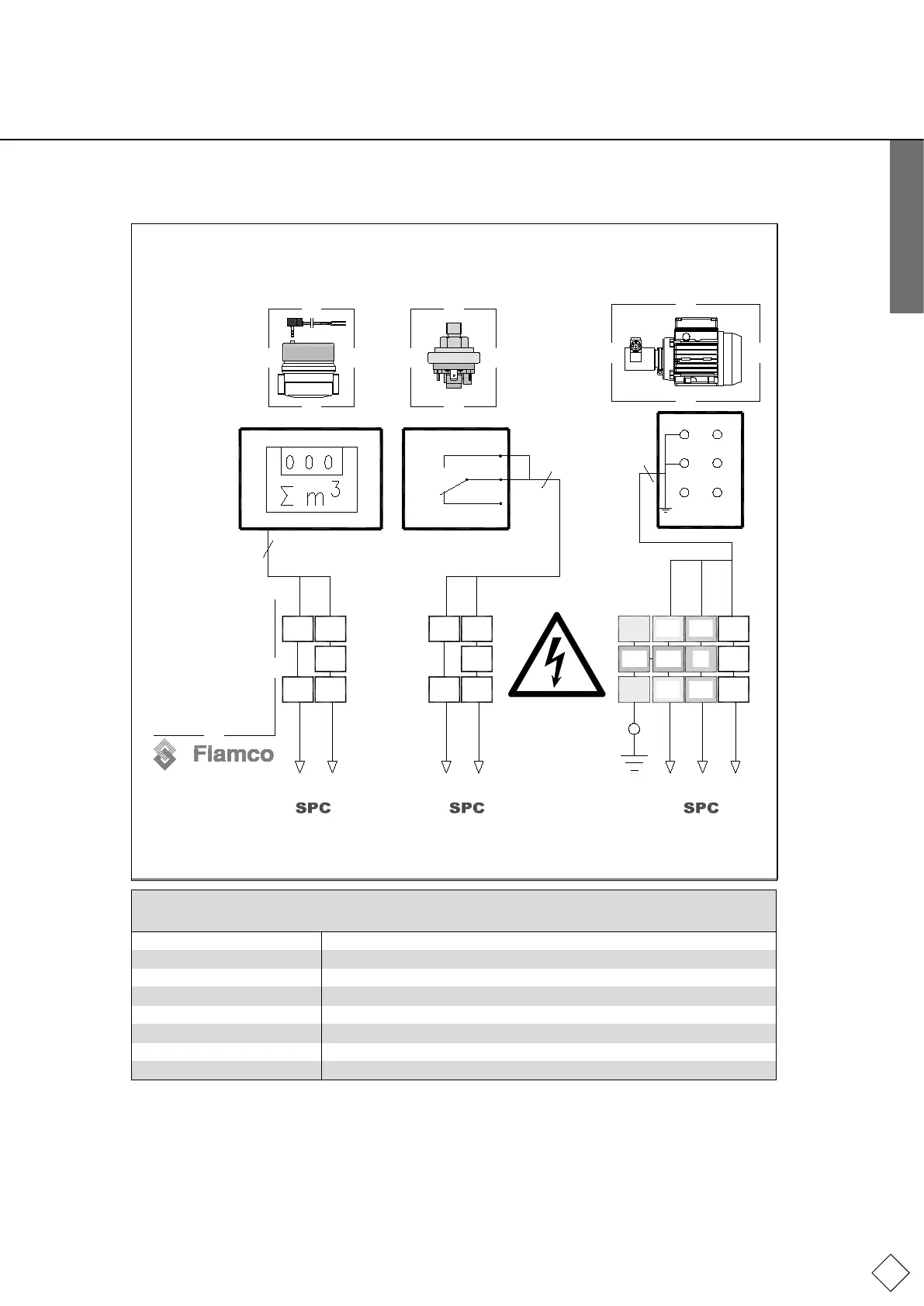
2.3 Terminal diagram
98
98
3 43 3
3 43 3
1 91 8 2 0
1 8 1 9 2 0
P E
3
(gegn)
u1
w2
v1
u2
w1 v2
1
2
3
4
bl
bn
3
2
1
2
2
N L
G N DG N D
pw m ps re fill/ dra in
04.01.13
( 230V 5 0 H Z )
8 9 3 3 3 4 1 8 1 9 2 0
P E
Watermeterwithpulser(IWZ) Dry-run protection Pump
(DS240)
Execution
As pressure switch
Conductor Color Code
bl Blue
bn Brown
ye/gn Yellow/Green
bl Black
wt White
gr Grey
External
pe
cable
connect to
housing
bn
bl
Ye/gn
bn
wt
Explanation of the abbreviations used in the terminal diagram
Please note: The switch settings shown represent the current-free, non-switched state.
extra-low voltage Protective low voltage
high voltage Voltage as per markings
L Phase
N Neutral wire
PE Protectiveearth(PE)conductor
Pumpe/pump Pump motor
ps Pressure switch
pwm Pulse water meter