TemplateA4_v20130506
14
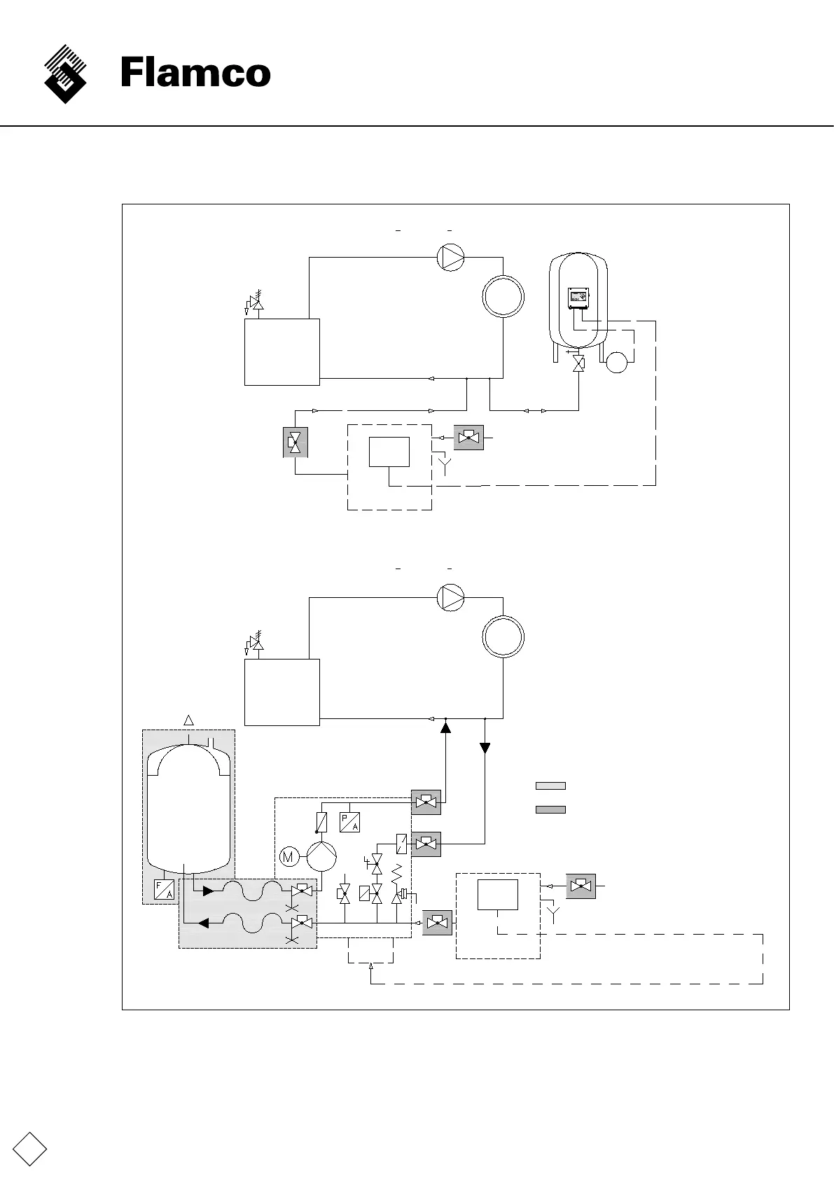
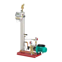
1.3 Sample installation diagram
M -K
L
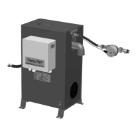
F la m c o -F I L L P
DN *
F la m c o -F I L L P
*
**
Supply temperature <105°C(STB<110°C)
Supply temperature <105°C(STB<110°C)
Example of level-
controlledllingwitha
Flamco-Fill P on a
Flexcon MK
Example of
level-controlled
llingwitha
Flamco-Fill P on a
Flexcon MK
Please note: If the
return line is routed horizontally, implement the
connectionfromabove(notfrombelow)toavoid
additional contamination
.
To be provided by the customer: System inlet,
system outlet,
llinginlet,componentcouplings.
Control unit
PLC
Terminal(8,9);33,34;18,19,20asperPLC
Filling water inlet
Coupling assembly *
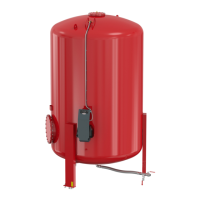
Basic vessel*
System supply
side
System supply
side
Control module Flamcomat *
Cap valve**
Cap valve**
Scope of supply, standard.
Accessories
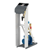
Compressor
pressure maintenance
unit with
PLC control
Heater
Heater
Terminal
box
Terminal
box
Filling water inlet
Terminal(8,9);33,34;18,19,20asperPLC
Hot leg
Hot leg
Cold leg
Cold leg