7 Connection PIOX S70x
UMPIOX_S7V4-6-3EN, 2018-10-10 79
PIOX S709
• Prepare the input cable.
• Connect the input cable to the terminals of the transmitter (see Fig. 7.3, Fig. 7.43 and Tab. 7.21).
At full load (20 mA), a voltage of 22.9 V DC (PIOX S704, S705) or 13.9 V DC (PIOX S709) is available for the supply of the
passive current source.
For the assignment and the activation of the current input see chapter 18.
7.5.3 Binary Input
The transmitter can be equipped with 1 or 2 binary inputs. Via the binary outputs, it is possible to remotely trigger some
functions of the transmitter (see section 12.10).
PIOX S704, S705
For the connection of the input cable to the transmitter see box Cable connection S. 72, Fig. 7.1 or Fig. 7.2, Fig. 7.41 or
Fig. 7.42 and Tab. 7.22)
.
PIOX S709
• Prepare the input cable.
• Connect the input cable to the terminals of the transmitter (see Fig. 7.3, Fig. 7.43 and Tab. 7.22).
7.6 Serial Interface
7.6.1 RS232 Interface
The RS232 interface is located on the front plate of the transmitter (see Fig. 7.44, Fig. 7.45 or Fig. 7.46).
• Connect the RS232 cable to the transmitter and to the serial interface of the PC. If the RS232 cable cannot be connected
to the PC, use the RS232/USB adapter.
The RS232 cable and the RS232/USB adapter are part of the serial data kit (optional).
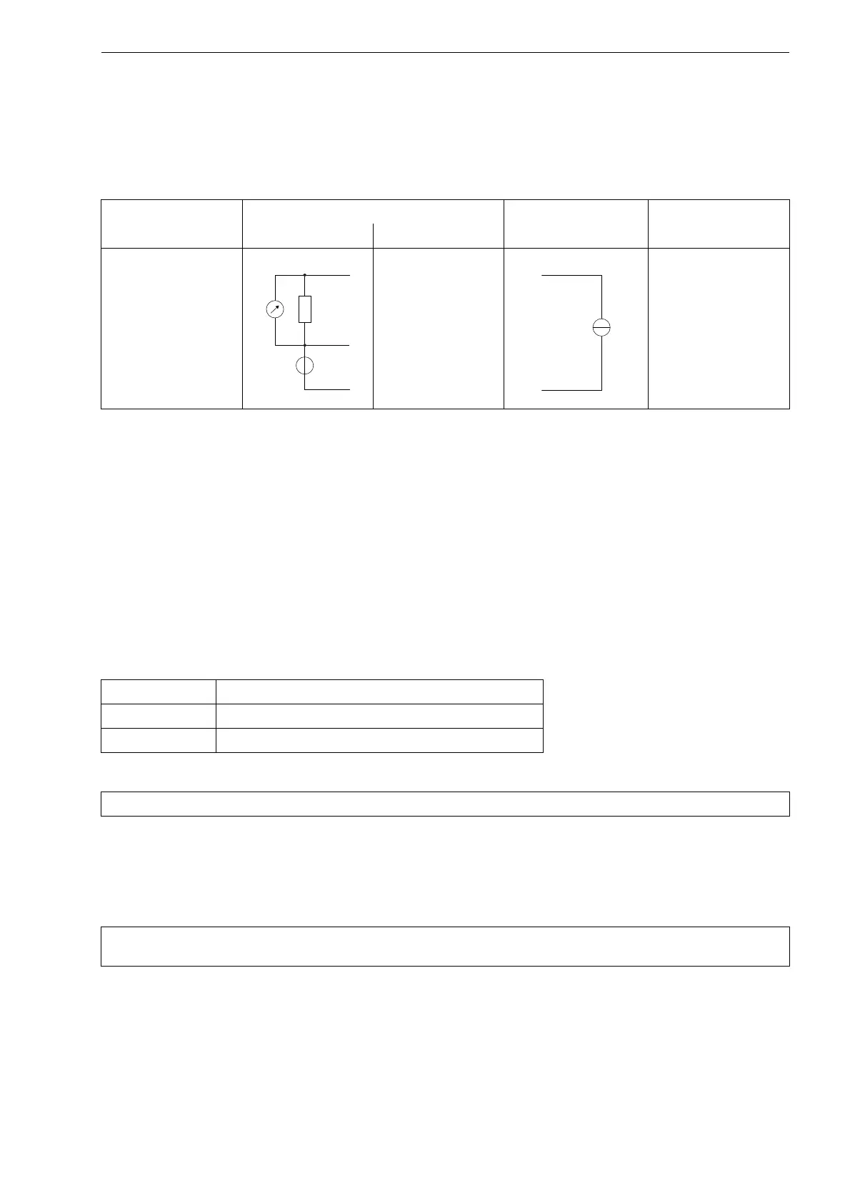
Tab. 7.21: Connection of a passive current source
input transmitter external circuit comments
internal circuit connection
current input
TxA
TxB (not connected)
Txb
max. permanent
overcurrent: 100 mA
Tab. 7.22: Connection of the binary inputs
binary input terminals
S1 P1+, P1-
S2 P2+, P2-
Attention! Observe the "Safety Instructions for the Use in Explosive Atmosphere" (see document SIFLUXUS).
Note! If a problem occurs when the RS232/USB adapter is used for the connection, contact your system
administrator.

 Loading...


