PIOX S70x 7 Connection
72 UMPIOX_S7V4-6-3EN, 2018-10-10
7.3 Power Supply
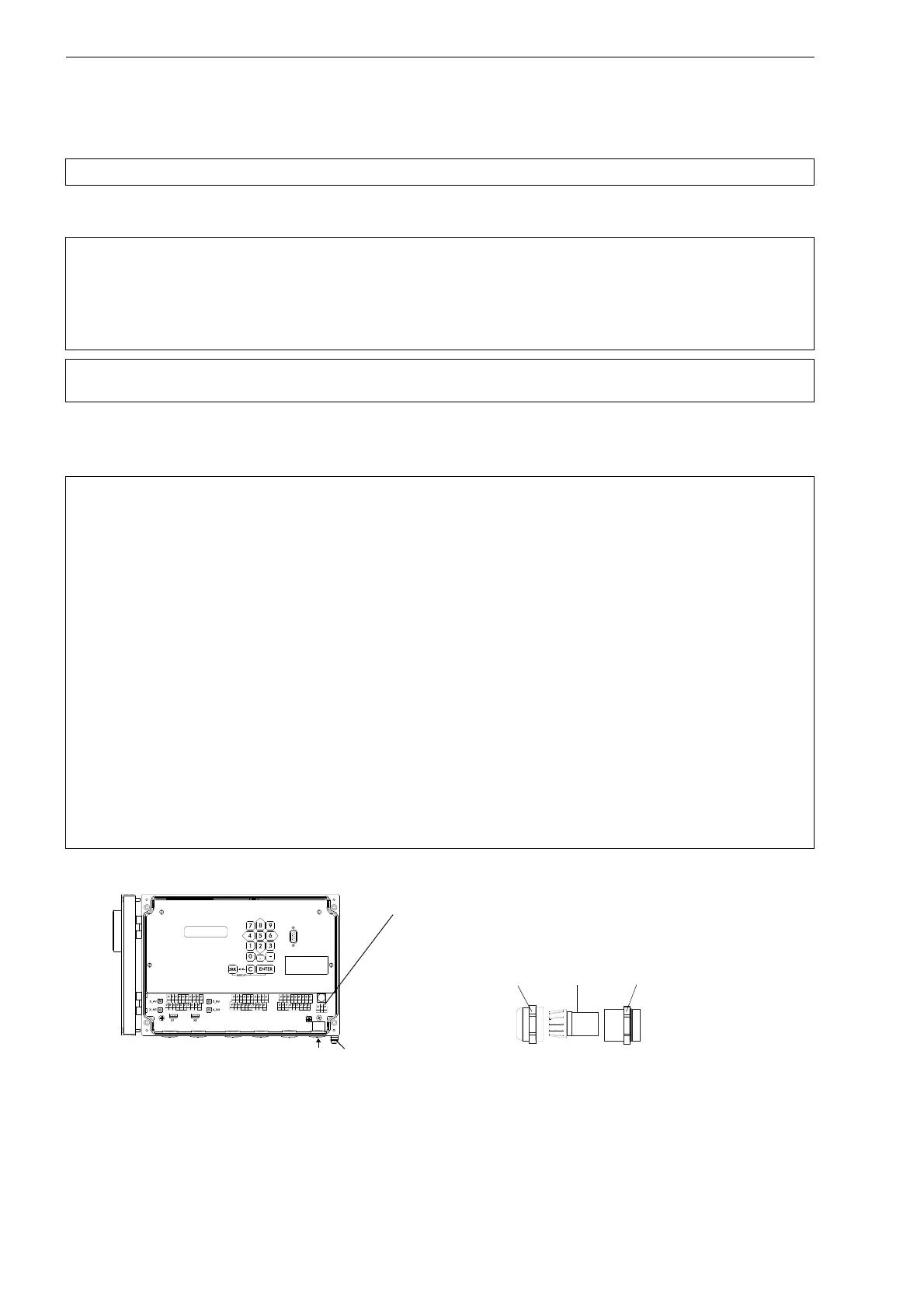
The external protective earth is connected to the equipotential bonding terminal on the housing of the transmitter PIOX
S704**-A2, S705**-A2, S705**-NN (see Fig. 7.35 or Fig. 7.36). It always has to be connected.
PIOX S704, S705
For the connection of the power cable to the transmitter, see box Cable connection, Fig. 7.1 or Fig. 7.2, Fig. 7.35 or Fig.
7.36 and Tab. 7.17
.
Attention! Observe the "Safety Instructions for the Use in Explosive Atmosphere" (see document SIFLUXUS).
Attention! According to IEC 61010-1:2010, a switch has to be provided near the measuring instrument in the
building installation, easily accessible for the user and marked as a disconnection device for the mea-
suring instrument.
If the transmitter PIOX S704**-A2, S705**-A2 is used in an explosive atmosphere, the switch should
be installed outside the explosive atmosphere. If this is not possible, the switch should be installed in
the least hazardous area.
Attention! The degree of protection of the transmitter will only be guaranteed if the power cable fits firmly and
tightly in the cable gland.
Cable connection
• Remove the blind plug from the transmitter for the connection of the cable (if present).
PIOX S704:
• Prepare the cable with an M20 cable gland.
• Push the cable through the cap nut, the compression part and the basic part of the cable gland.
• Insert the cable into the housing of the transmitter.
• Screw the gasket ring side of the basic part into the housing of the transmitter.
• Fix the cable gland by screwing the cap nut onto the basic part.
• Connect the cable to the terminals of the transmitter.
PIOX S705:
• Prepare the cable with a cable gland.
• Push the extension cable through the cap nut, the compression part, the basic part and the gasket ring.
(Sealing ring: only for cable gland M20, not for cable gland 1/2 NPS.)
• Insert the cable into the housing of the transmitter.
• Fix the cable gland by screwing the cap nut onto the basic part.
• Fix the transducer cable by tightening the cable gland with the ferrite nut.
• Connect the cable to the terminals of the transmitter.
Fig. 7.35: Transmitter PIOX S704
AVSAV
AGN
ARS
AR
BVSBV
BGN
BRS
BR
SA1
SA2
SA3
SA4
SB1
SB2
SB3
SB4
T1a
T1b
S2 T2a
T3a
T3b
S4
T4a
T2b
T4b
T1A
T1B
S1 T2A
T3A
T3B
S3
T4A
T2B
T4B
A+
B-
P1+ P2+
P4+
P5a
P6a P7a
P3+
101
103
P1- P2-
P4-
P5b
P6b
P7b
P3-
PE
N(-)
L(+)
cable gland
cap nut
compression part basic part
power supply
equipotential bonding terminal
(PIOX S704**-A2)

 Loading...


