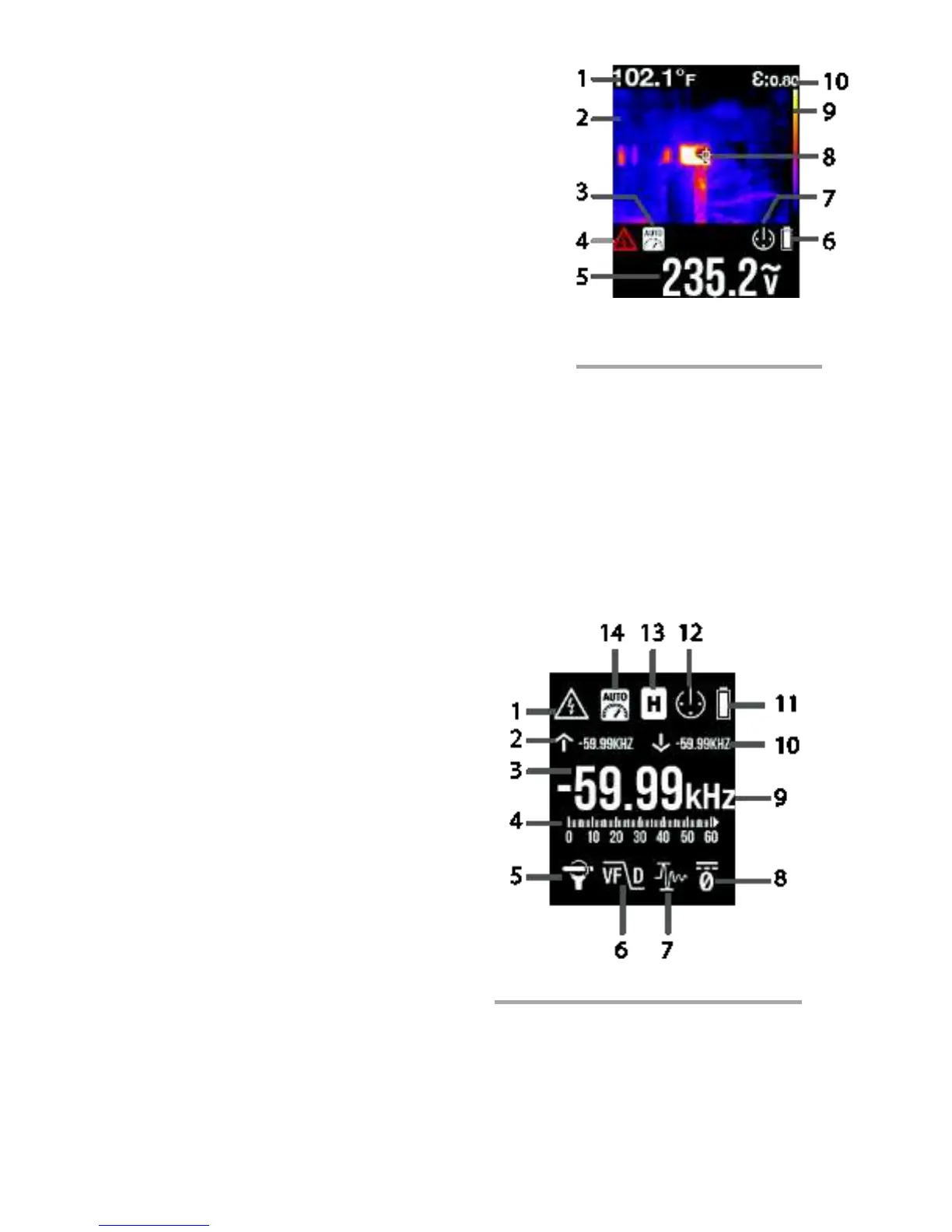
4.5 Thermal Image Display
Press the IGM button to open the Thermal Imager.
Refer to Section 5.9 for detailed instructions on the
IR Thermal Imager functions. Note the clamp meter
display information in the thermal image example
screen Fig. 4-3.
1. Temperature Measurement*
2. Thermal Image
3. Auto Range icon
4. High Voltage alert
5. Voltage reading
6. Battery status
7. Auto Power OFF active
8. Cross hairs
9. Palette scale
10. Emissivity setting
*Temperature display area shows dashes while the reading is stabilizing.
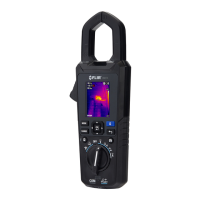
4.6 Clamp Meter Display
1. High Voltage alert
2. MAX reading
3. Digital representation of measurement
4. Bargraph representation of measurement
5. Clamp Adaptor icon
6. Low Pass Filter icon (VFD mode)
7. Inrush Current mode
8. DCA Zero mode icon
9. Unit of measure
10. MIN reading
11. Battery status
12. Auto Power OFF (APO)
13. Data Hold icon
14. Auto Range icon