EasyManuals Logo

FLIR CM174 User Manual

FLIR CM174
38 pages
To Next Page IconTo Next Page
To Previous Page IconTo Previous Page
Page #8 background imageLoading...
Page #8 background image
FLIR CM174 USER MANUAL Document Identifier: CM174-en-US_AC
8
4. Meter Description
4.1 Meter Parts
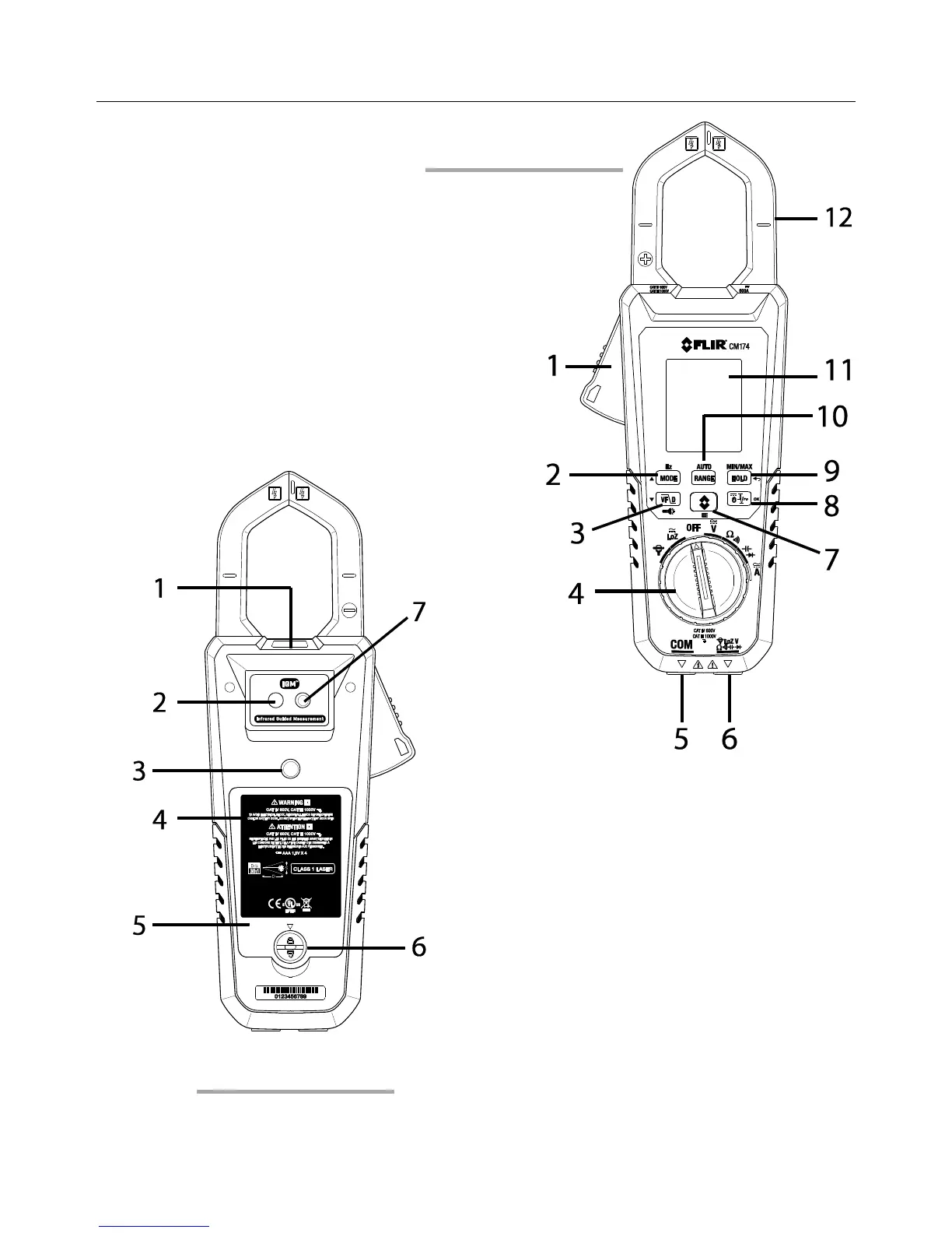
1. Jaw opening trigger
2. MODE/Hz/up arrow button
3. VFD/Work light/down arrow button
4. Function switch
5. COM (negative -) Probe Input jack
6. Positive (+) Probe Input jack
7. IGM Thermal Image mode button
8. DCA Zero/Inrush/OK button
9. MIN/MAX HOLD button
10. AUTO/RANGE Button
11. Color TFT Display
12. Clamp jaw
1. Work light
2. Thermal imaging lens
3. Tripod mount
4. Warning & informational text
5. Battery compartment
6. Battery compartment lock
7. Laser pointer lens
Fig 4-1 Front View
Fig 4-2 Rear View

Other manuals for FLIR CM174

Questions and Answers:

Question and Answer IconNeed help?

Do you have a question about the FLIR CM174 and is the answer not in the manual?

FLIR CM174 Specifications

General IconGeneral
BrandFLIR
ModelCM174
CategoryMeasuring Instruments
LanguageEnglish

Related product manuals