5.10 IGM Thermal Imager
Warning: Do not point the laser toward the eyes, as prolonged exposure may cause
injury.
5.10.1 Thermal Imager Basics
In the Thermal Imaging mode the user can measure a targeted surface’s temperature.
This is accomplished by detecting the energy emitted by the surface under test. A
thermal image of the area under test is viewed in the same manner as with dedicated
thermal imaging devices, where color variations reflect temperature variations. See
Section 5.10.3 for an in-depth discussion on Infrared Energy and Thermal Imaging
Theory. The laser pointer and display cross hairs assist in surface targeting.
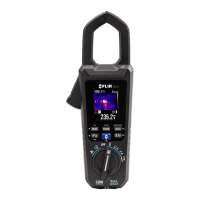
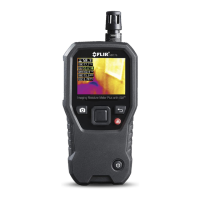
Press the IGM button to open the Thermal
Imager. In Fig 5-8 the meter is set to color
palette IRON. Select other palettes in the
Programming Menu.
1. Temperature Measurement
2. Thermal Image
3. Auto Range icon
4. High Voltage alert
5. Voltage reading
6. Battery status
7. Auto Power OFF active
8. Cross hairs
9. Palette scale
10. Emissivity setting
The Temperature measurement (1) shown on the upper left corner of the display
represents the temperature of the spot sensed. Note that while the temperature
reading is stabilizing dashes will be displayed for approximately 30 seconds. The
Laser and the Cross hairs (8) can be used for precise targeting (set them ON or OFF
individually in the Programming Menu).
The currently selected Emissivity value (10) is shown on the upper right corner. Use
the programming Menu to change the emissivity setting. See the Emissivity table
later in this guide for a list of settings for various surface textures.
The Thermal scale (9) shows the range of colors for thermal images. The lighter the
color, the warmer the temperature; the darker the color, the cooler the
temperature.
The Distance to Spot ratio for the imager is 30:1 meaning that the measurement
spot is 30 times smaller than the distance the meter is from spot (at a distance of
30”, the meter ‘sees’ a target spot of 1”). See Fig 5-8 for examples. The thermal
imager’s FOV (Field Of View) is 50 degrees (top view) and 38.6 degrees (side view),
see Fig. 5-9 (a) and (b).