To customize the Thermal Imager use the programming menu as described in Section
5.10.2. For basic operation follow these steps:
1. Set the function switch to any position.
2. Press the IGM button for < 1 second to switch the IGM Thermal Imager ON. Point the
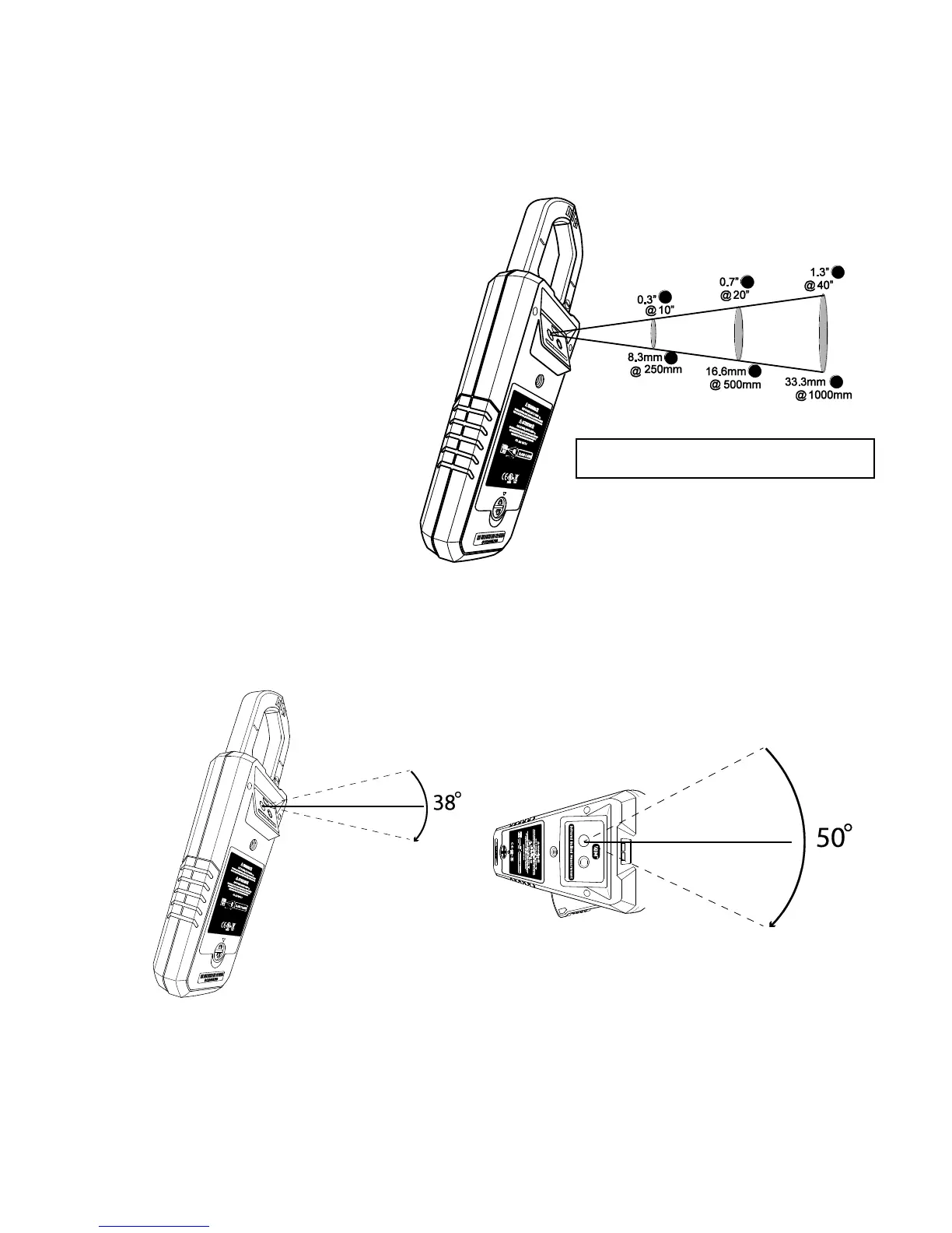
thermal imaging lens (located
on the rear of the meter)
toward an area to measure.
3. The display will show the
temperature measurement in
the upper left hand corner for
the targeted area and the
currently selected emissivity
value on the upper right hand
corner.
4. In the Thermal Imaging mode,
the laser pointer and display
cross hairs can be used to
assist in targeting. These tools
can be switched ON or OFF in
the Programming Menu.
5. In the Thermal imaging mode, the meter continues to operate normally as a clamp
meter allowing any of the electrical functions to be used. Note that in the Thermal
Imaging mode the electrical functions are shown on the lower portion of the display
beneath the thermal image (see Fig. 5-8).
Fig. 5-10 (a) Field of View – side view Fig. 5-10 (b) Field of View - top view