5.4 Voltage and Current Measurements
Note: If the measured voltage is greater than 30 V DC or AC RMS, the indicator is
displayed.
5.4.1 Basic Voltage Measurements
1. Set the function switch to the V position.
2. To manually select AC or DC, press the MODE button.
3. To manually select the measurement range (scale), press the RANGE button
repeatedly. Refer to section 5.2 Auto/Manual range mode.
4. Insert the black probe lead into the negative COM terminal and the red probe
lead into the positive V terminal.
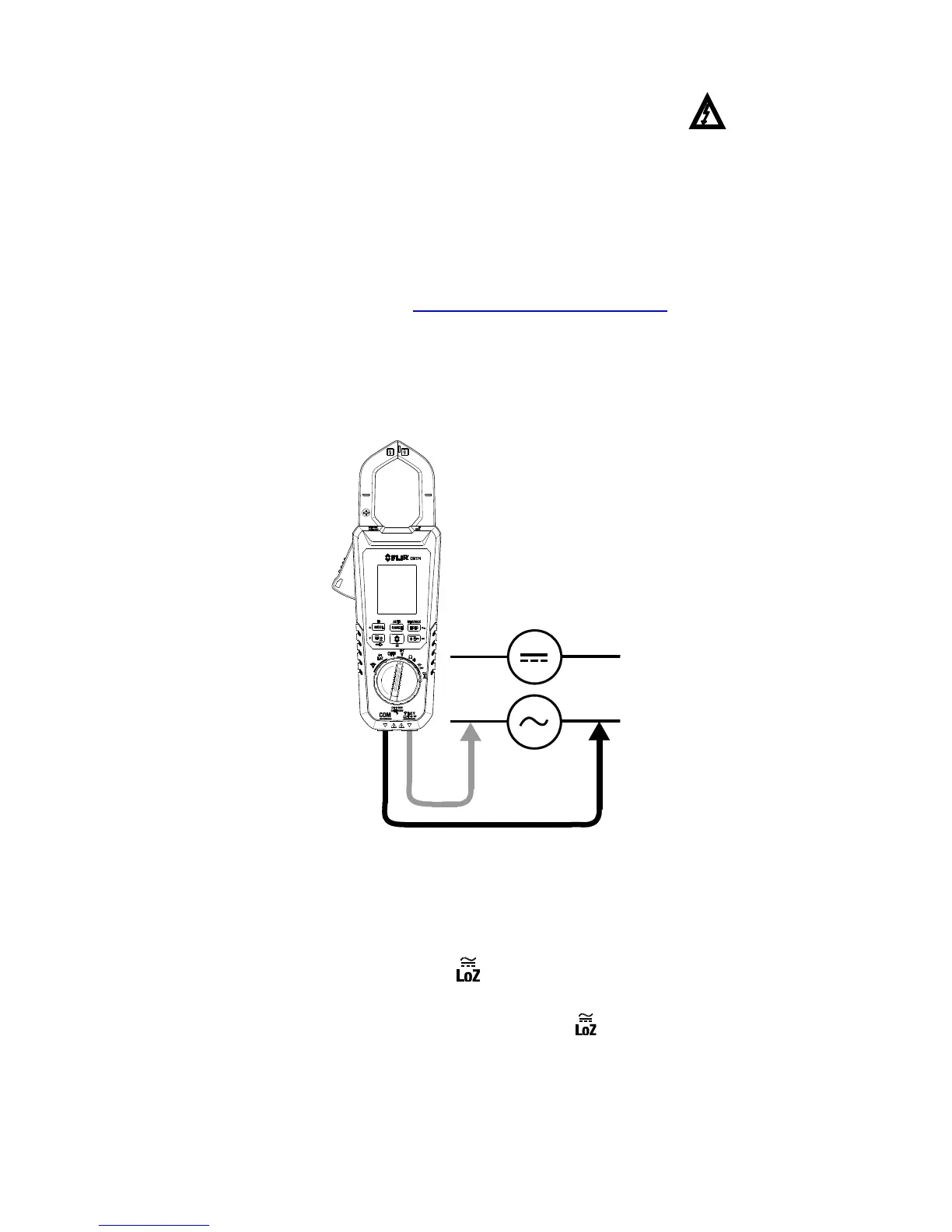
5. Connect the probe leads in parallel to the part under test.
6. Read the voltage value on the display.
Figure 5.1 Voltage Measurements
5.4.2 ‘Lo Z’ Voltage Measurements
When the function switch is turned to the position, the meter incorporates a low
impedance circuit that eliminates ghost voltages. The low impedance is approx. 2.5kΩ. To
take voltage measurements in the Lo Z mode, select the function switch position and
follow the voltage measurement instructions in the previous section.