5.5 Resistance Measurements
Warning: Do not perform resistance tests before removing the power from resistors and
other devices under test during a measurement. Injury to persons can occur.
1. Set the function switch to the position.
2. Use the MODE button to select the resistance mode (continuity symbol
should be OFF).
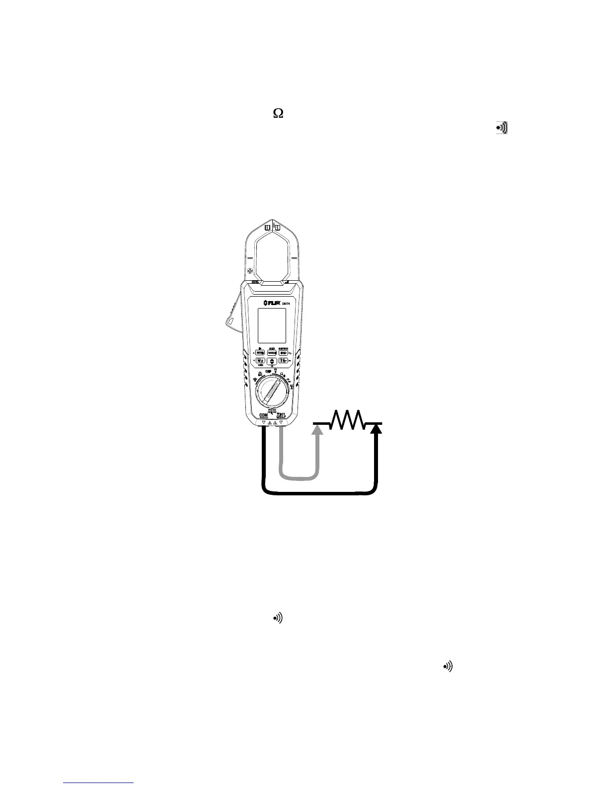
3. Insert the black probe lead into the negative COM terminal and the red probe
lead into the positive Ω terminal.
4. Touch the tips of the probe across the circuit or component under test.
5. Read the resistance value on the display.
Figure 5.5 Resistance and Continuity Measurements
5.6 Continuity Test
Warning: Do not perform continuity tests before removing the power to the component,
circuit, or other device under test during a measurement. Injury to persons can occur.
1. Set the function switch to the position.
2. Insert the black probe lead into the negative COM terminal and the red probe
lead into the positive Ω terminal. Refer to Fig. 5-5 for connection example.
3. Use the MODE button to select continuity measurement. The indicator will be
displayed.
4. Touch the tips of the probe across the circuit or component under test.
5. If the resistance is lower than 30 Ω, the meter will beep.