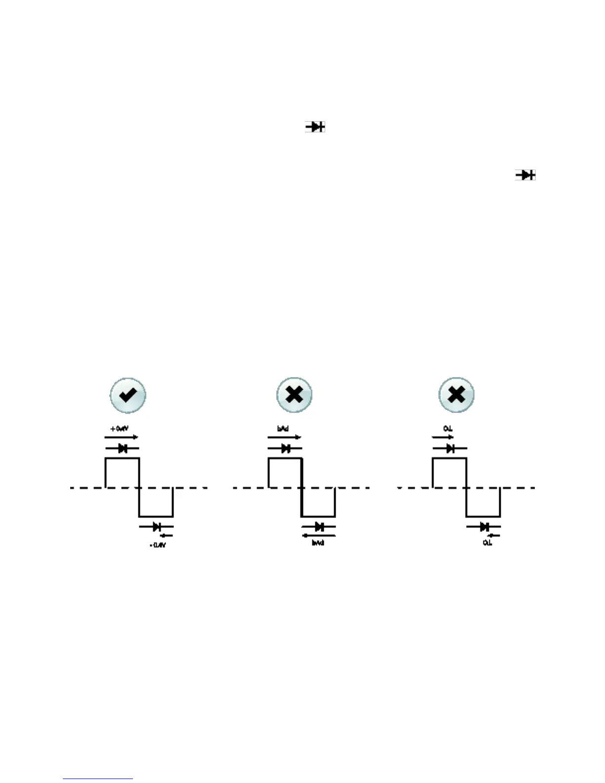
5.9 Diode Test (SMART mode)
Warning: Do not perform diode tests before removing the power from capacitors and
other devices under test during a measurement. Injury to persons can occur.
1. If not already selected, choose SMART Diode test mode in the Programming
Menu (See Section 5.10.2).
2. Set the function switch to the diode position.
3. Insert the black probe lead into the negative COM terminal and the red probe
lead into the positive Ω terminal.
4. Use the MODE button to select the diode test function. The diode indicator
will be displayed.
5. Touch the tips of the probe across the diode or semiconductor junction under
test.
6. If the reading is between ± 0.40 and +0.80V, the component is good; BAD or O.L
displays indicate a defective component.
In SMART Diode mode the CM174 checks diodes using an alternating test signal sent
through the diode in both directions. This allows the user to check the diode without
having to reverse polarity manually. The meter display will show ± 0.4 ~ 0.7V for a good
diode, BAD for a shorted diode, and O.L for an opened diode. See Fig. 5.7 below:
Figure 5.7 Diode Test in the SMART mode