List of Figures
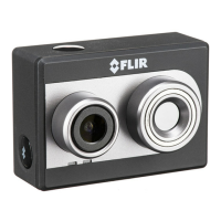
Figure 1. Duo with Camera Mount ............................................................................................................................5
Figure 2. Bench Cable ...............................................................................................................................................6
Figure 3. Core dimensions .........................................................................................................................................8
Figure 4: Mini-USB 10-pin Layout ............................................................................................................................9
Figure 5. Camera Status and Record LED Description ...........................................................................................10
Figure 6: FLIR launch screen ...................................................................................................................................12
Figure 7. Home Screen ............................................................................................................................................13
Figure 8. Thermal IR Color Palettes ........................................................................................................................15
Figure 9. Video Display mode selection .................................................................................................................16
Figure 10: Video/Still Images and Record, shown in Still Images mode at 5-second intervals. ..............................17
Figure 11. Main Settings (Radiometry and Spot Meter function (Duo R only) not shown) ...................................19
Figure 12. Radiometry Tab ......................................................................................................................................21
Figure 13. Spot Meter OSD, with “Temperature Unit” set to Fahrenheit ...............................................................22
Figure 14. About Page .............................................................................................................................................24
Figure 15. PixHawk Flight Controller for PWM .....................................................................................................26
Figure 16. PWM Settings allow for control of Recording (start/stop and mode), IR Color Palette selection,
Recalibrate, and streaming Display Video Mode .............................................................................................27
Figure 17. Function Selection ..................................................................................................................................28
Figure 18. PixHawk Flight Controller for MAVLink .............................................................................................29
Figure 19: FLIR Tools can be used for advanced thermal analysis on Radiometric JPEGS ...................................33