EasyManua.ls Logo

fluenta FGM 160 User Manual

fluenta FGM 160
40 pages
To Next Page IconTo Next Page
Page #1 background imageLoading...
Page #1 background image
Document number:
62.120.001
Document title:
FGM 160 Installation and Hook-Up
Instructions
Scope:
ISO 9001:2008 §7.2.3
Additional Information (when applicable)
F
2016.03.01
Draining plug note added
MW
MW
E
2014.07.14
Updated installation guidelines
MS
KP
D
2013.11.29
Proofread and updated
MR
MW
C
2013.02.14
Removed from User Manual, updated:
changes in content.
KH
MW
B
2009.05.29
Updated information
DIÅ
AAJ
A
2007.11.26
Issued for Fluenta release; moved to User
Manual
DIÅ
AAJ
Rev.
index
Issue date
Reason for issue
Review
Approved
Replacement for:
Total pages:
40
Fluenta source doc.
(for translations):

Table of Contents

Other manuals for fluenta FGM 160

Question and Answer IconNeed help?

Do you have a question about the fluenta FGM 160 and is the answer not in the manual?

fluenta FGM 160 Specifications

General IconGeneral
Brandfluenta
ModelFGM 160
CategoryMeasuring Instruments
LanguageEnglish

Summary

Purpose

Abbreviations and Definitions

Abbreviations

Defines abbreviations used in the document, such as FGM and TFS.

Definitions

Provides definitions for key terms like Metering Spool Section, Cold Tapping, Hot Tapping, etc.

General Information

Unpacking and Inspection

Inspection of Goods

Mandatory inspection of supplied goods for damage and verification against packing list.

Ex-Classification Marking

Ensures FGM 160 is certified for the intended hazardous zone.

Transducer/Probe Installation

Installation of Transducer Holders

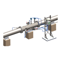
Describes three methods for mounting transducer holders: spool piece, cold tapping, and hot tapping.

Space Requirements

Details pipe straight section length and distances from upstream/downstream disturbances.

Cold Tapping Procedure

Details the process of cold tapping, including spot marking and centerline finding.

Transducer Mounting and Alignment

Covers using sighting tools for alignment, edge flush mounting, and insertion procedures.

Field Computer Installation

Mounting Frame and Wiring Basics

Details field computer mounting frames and general electrical wiring procedures and cable preparation.

Transmitter and Data Connections

Covers connecting pressure/temperature transmitters and control room data cables.

Output Signal Configurations

Explains configuration of 4-20mA current loop, HART, pulse, frequency, and level outputs.

Upgrading from FGM 130

References

Appendix I: Space Requirements for TFS