6.1 The Field Computer Mounting Frame
The field computer can be mounted on existing infrastructure, or a custom mounting frame.
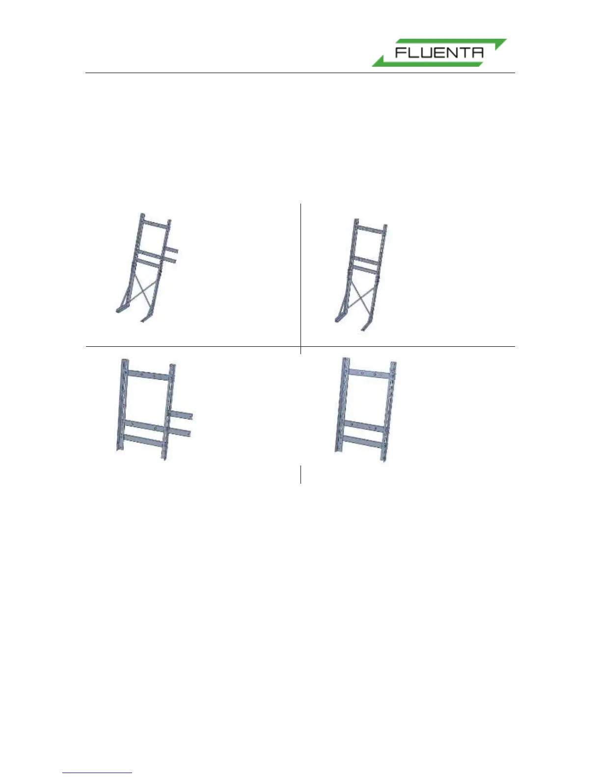
The custom mounting frame comes in four versions. The first is shown in Figure 30 a), and
includes legs for a free standing mount, as well as two frames for mounting a separate AC to
DC converter in an Ex-d housing. The frame shown in b) is the same, except it does not
include a mounting frame for an AC to DC converter. The mounting frame in d) shows a
frame that mounts onto the existing infrastructure. The frame in c) shows the same frame as
d) with a frame for an AC to DC converter.
Figure 30: The FGM 160 Field Computer mounting frame versions.
6.2 Electrical Wiring
Before the installation starts, power and signal cables between the FGM 160 and the local
equipment room should be pulled and ready for termination. Normally, the routing and
preparation of the cables are not part of Fluenta’s scope of work.
External wiring is to be carried out according to:
FGM 160 – Field Wiring Diagram, Fluenta Doc.no.: 77.120.509 [3].
Power source should not be connected until verification of supply voltage has been
performed. Main fuses should not be inserted at any stage of the installation phase
All cables should be connected to the terminals in the Ex-e enclosure of the FGM 160.
The blue terminals are IS (Intrinsically Safe) and are connected to the field computer through
internal IS barriers. The gray terminals are not connected to an IS barrier, and are meant for
signals between the field computer and safe area equipment and systems.