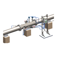
Figure 23: A schematic of the gas-proof measuring tool.
5.3.2 Edge Flush Transducer Mounting
5.3.2.1 Setting the correct insertion depth
The insertion depth measurement should be performed as usual. When setting the insertion
depth, remember that the retraction of the transducer means that the insertion depth should
be reduced (see Figure 24).
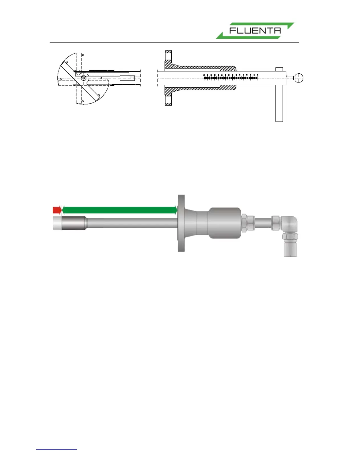
Figure 24: Insertion depth.
The insertion depth (green arrow) must be reduced (red arrow) according to the angle of the
transducer holder
As a result of the reduced insertion depth, the distance between the transducer tips will
increase (see Figure 25). The transducer tip distance is a parameter that directly affects the
flow velocity calculations, therefore the transducer distance must be updated in the
configuration of the flow computer.
For the FGM 160, the transducer distance can be found in the O&S Console software under
Config – Config Main Page – Mechanical Parameters – Measured (length in m).