When using the sighting tool for pipes that are 10” and less, use the measurement from the
special tool as described in section 5.3.1 to find the correct depth for the transducer. This
depth should be the same for the sighting tool. Measure from the narrow end of the sighting
tool and tighten the stop washer at that position. Insert the sighting tool so that the stop
washer is flush with the flange on the transducer holder, this is shown in Figure 18. There is
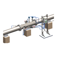
a groove in the head of this type of sighting tool shown in Figure 19. Align one sighting tool
with the pipe, and rotate the other until the light is visible. Adjust the sensor holder so that the
circle of light is seen as described below.
Figure 19: Look through the holes on the sighting tool. Rotate the sighting tool on the left to
get a correct alignment.
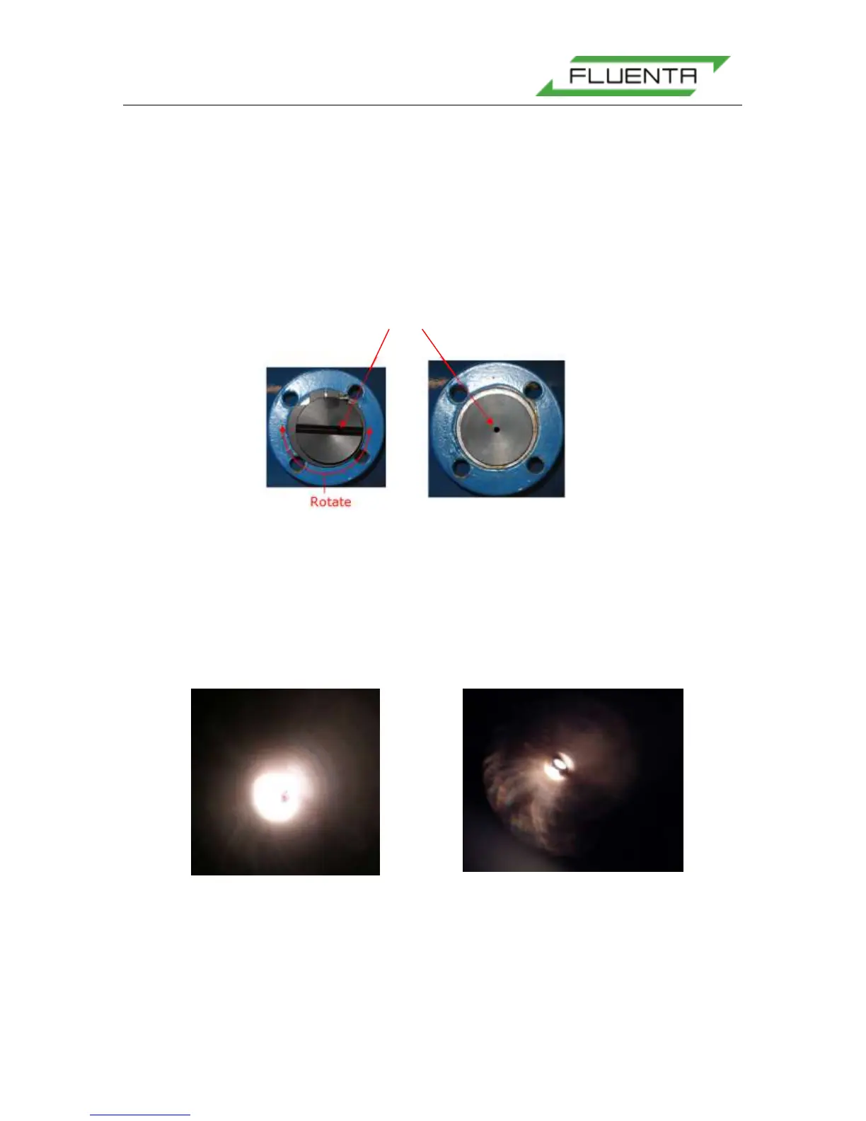
When the transducer holders are properly aligned and the sighting tools are inserted, it is
possible to see a perfect circle of light when looking through the hole in one of the sighting
tools, shown in Figure 20. If there is not enough ambient light, it may be necessary to shine a
light source through the hole in the opposite sighting tool.
5.2.4 Hot Tapping Transducers Full Size, TFS
If hot tapping is needed, use the same procedure as described in “Cold Tapping” but do not
drill the pilot holes. When the welding of the transducer holders has been performed and the
ball valves are mounted, connect the hot-tapping equipment to the 2" ball valve. Open the
Visual check