FGM 160 Installation and Hook-Up Instructions
1. PURPOSE
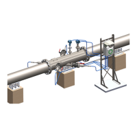
The purpose of this procedure is to provide a traceable point-by-point installation guideline
for the Fluenta Flare Gas meter, Field Computer (FGM 160) system. This document provides
details on the different options that are available on the FGM 160 system, the installation
of the base system, and the optional configurations. The optional configurations include the
two types of transducer, possible upgrade from previous Fluenta Flare Gas Meters, and the
different interfaces available from the Flow Computer to the Plant Control System.
The procedure also provides a means to establish an “Installation and Hook-Up Record”
to document the installation.
2. ABBREVIATIONS / DEFINITIONS
2.1 Abbreviations
FGM Flare Gas Meter
TFS Transducer Full Size
2.2 Definitions
A section of pipe that has the transducer, pressure, and
temperature holders already mounted.
Mounting the transducer, pressure, and temperature holders
on a section of the flare pipe which has been shut off from the
flare system.
Mounting the transducer, pressure, and temperature holders
on a section of the flare pipe which is an active part of the flare
system.
The center of the tip of the transducer is flush with the inner
wall of the pipe.
The part of the transducer tip that is inserted furthest into the
transducer holder/ball valve, and is flush with the inner wall
of the pipe.
The distance from the tip of the transducer to the raised part
of the transducer flange.