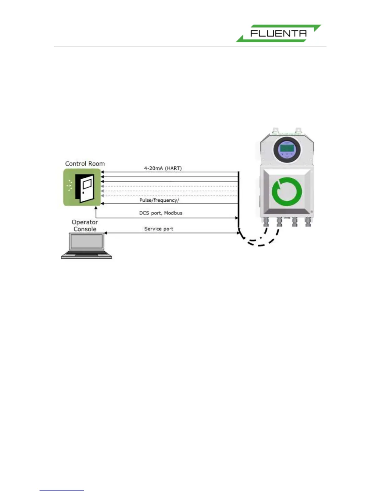
6.2.5 Control Room and Data Cables
The FGM 160 Flow Computer can be connected to the control room in several different
ways. These allow the DCS or SCADA software in the control room to communicate with the
FGM 160 Flow Computer. The connection options are as follows:
• DCS port, Modbus protocol (RS-485)
• Three (3) 4-20 mA, with additional three (3) as option.
• HART interface (optional).
• One (1) Pulse, Frequency or Level output (optional).
Figure 38: Data and Signal Cables.
The Service port is for the Operator & Service Console. This connection must be available
in the safe area in order to enable Fluenta support personnel to check the meter’s
performance, configure the meter and upload new firmware. Figure 38 shows the different
connections. Normally, Operator Console and DCS wiring is not a part of Fluenta’s scope
of work.
6.2.5.1 DCS Port, Modbus
The FGM 160 can be interfaced to a DCS Modbus system by an RS 485 signal interface.
Normally a 2-wire interface is used, but 4-wire interface can also be used.
For detailed information regarding the DCS port wiring, please refer to:
FGM 160 – DCS Modbus Interface Specifications [4].
DCS Modbus Interface is disabled in FGM 160 Foundation Fieldbus configuration
6.2.5.2 Foundation Fieldbus Output
In FGM 160, FF configuration 4-20mA Outputs are not available. They are replaced by
Foundation Fieldbus Outputs. Wires for FF should be connected to FF_1 and FF_2 outputs
marked on the Figure below.