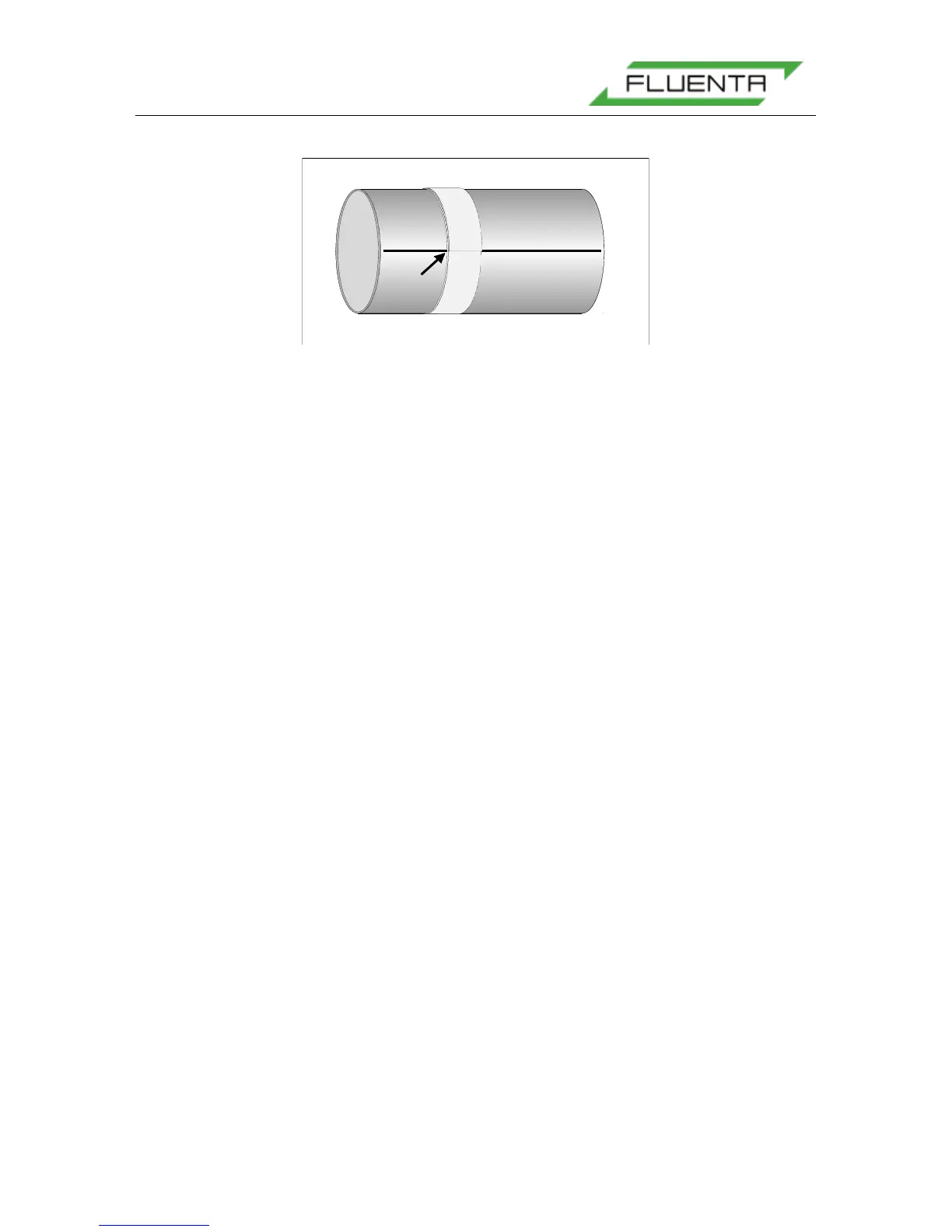
Figure 8: Marking a line around the pipe using a marking band.
Mark the hole for the sensors on the pipe wall following the inside rim of the transducer
holder when they are mounted in the welding-jig. Repeat the procedure for the other
transducer holder. The holes can now be cut according to the marked line on the pipe-wall.
After the holes are cut, ensure that the inner edges are grinded to be smooth, and beveled in
the correct way, ref. Figure 9. Before the welding starts, the groove angle must be grinded on
the holders. Normally the holders must be taken off the welding-jigs for grinding/adjustment
to get the right opening and joint, ref. Figure 10.