FGM 160 Installation and Hook-Up Instructions
5.2.3 Using the Sighting Tool
There are two types of sighting tool, one for each angle set. The first type, shown in Figure
15, is for transducer holders mounted at a 45° angle. There are two tools in a set, one fits
tightly in each transducer holder. Each of the tools has a hole in the center.
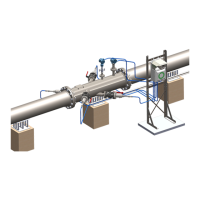
Figure 14: The
sighting tool
for the 42°/48°
transducer
holders
Figure 15: The sighting tool for 45°
transducer holders.
Figure 16: The stop
washer for the
sighting tool for the
42°/48° transducer
holders.
The second type of sighting tool is made for transducer holders that are mounted on pipes
with a diameter of 10” and less and with 42°/48° transducer holders, ref. Figure 14. This set
of tools uses the path of light for verification like the first. As the transducer holder’s mounting
angles are not equal, these tools require some adjustments before they can be used. The set
comes with a pair of stop washers, shown in Figure 16. The tool must penetrate the
transducer holder to the same depth as the transducer.
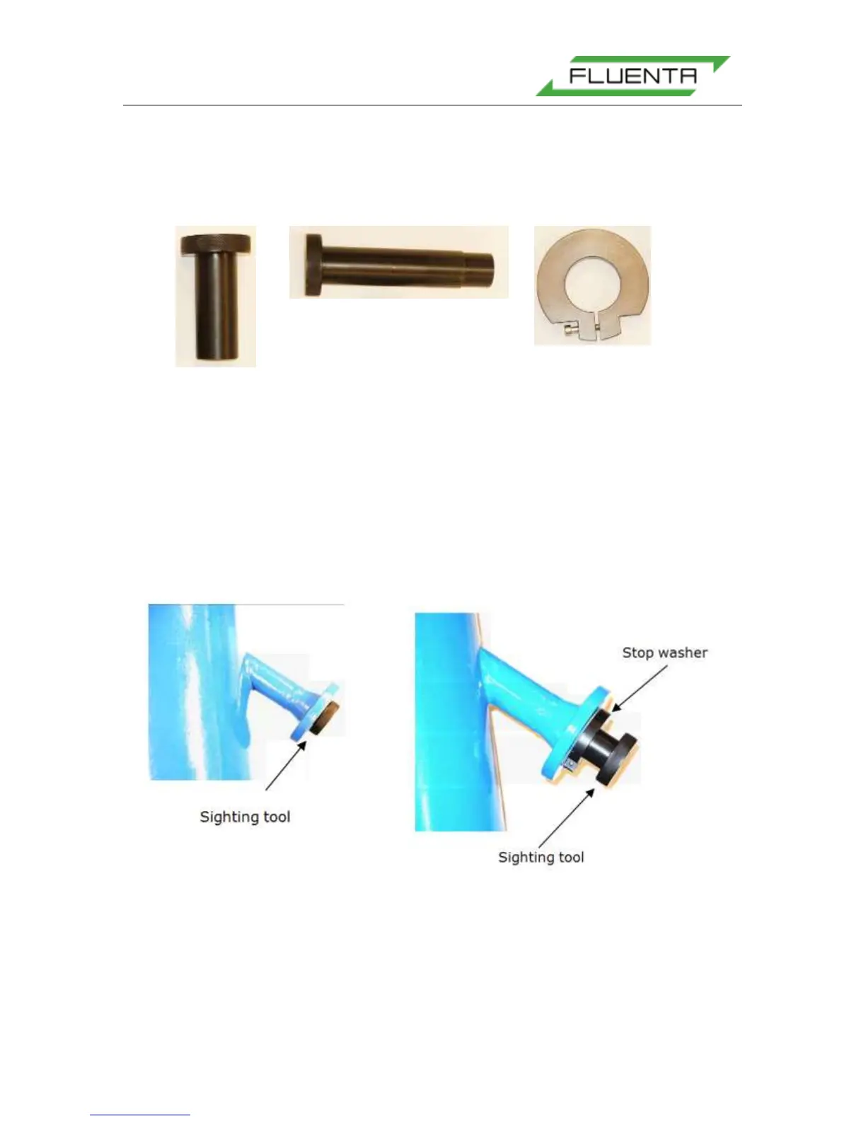
When using the sighting tool for pipes that have a diameter greater than 10”, insert the
sighting tool into the transducer holder so that the flange of the sighting tool is flush with the
flange of the transducer holder. This is shown in Figure 17.
Figure 17: A 45° sighting tool
mounted in a transducer holder.
Figure 18: A 42°/48° sighting tool with stop
washer mounted in a transducer holder.