User Manual F012-P
Page 50 FW_F012-P_M_v0501-01_EN
APPENDIX B - TROUBLESHOOTING
Table 1 lists and describes how to troubleshoot problems that can occur when installing or operating
the F012-P.
Table 2 lists internal alarm codes and conditions signaled by a blinking ALARM flag on the display
(
). Press the SELECT key several times to display the 4-digit error code shown in Table 2.
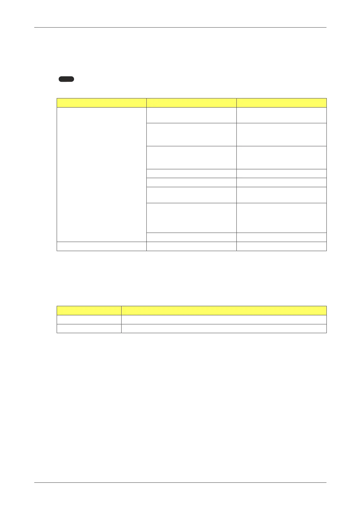
Table 1: Install and configuration errors
Observation Possible cause Check
No flow is detected while there
is flow
Wrong signal selection in
SETUP menu
5.1: FLOWMETER > SIGNAL
Unit or Time unit not matching
flow
2.1: FLOW RATE > UNIT
2.2: FLOW RATE > TIME UNIT
2.3: FLOW RATE > DECIMALS
K-factor setting wrong 2.4: FLOW RATE > K-FACTOR
2.5: FLOW RATE > DECIMALS K-
FACTOR
Calculation window too big 2.6: FLOW RATE > CALCULATION
Cut-off period wrong 2.7: FLOW RATE > CUT-OFF
LCD update period too long 4.1: POWER MANAGEMENT > LCD
UPDATE
Electrical connections wrong
Note: sensor input connectors
depend on Type
Terminals 1-3 (6): flowmeter
input[»28]
Terminals 5-7: flowmeter
input[»33]
Sensor not working properly Sensor
Pass code is unknown Call your supplier
An ALARM condition will in most cases be handled internally. If all programmed and measured
values appear to be correct, intervention by the Operator is not necessary.
If an ALARM occurs more often or stays active for a longer period, please contact your supplier.
When multiple alarms occur, the error code shown is the sum of the error codes as given below. For
example 0003 is a combination of error code 0001 and 0002.
Table 2: Internal alarms
Alarm Explanation
0001 Display error - Data on display might be corrupt
0002 Data storage error - Programming cycle might have gone wrong