Fluke 190-104/190-204
Service Information
4-26
4.6.15 Input D Trigger Sensitivity Test
Proceed as follows to test the Input D trigger sensitivity:
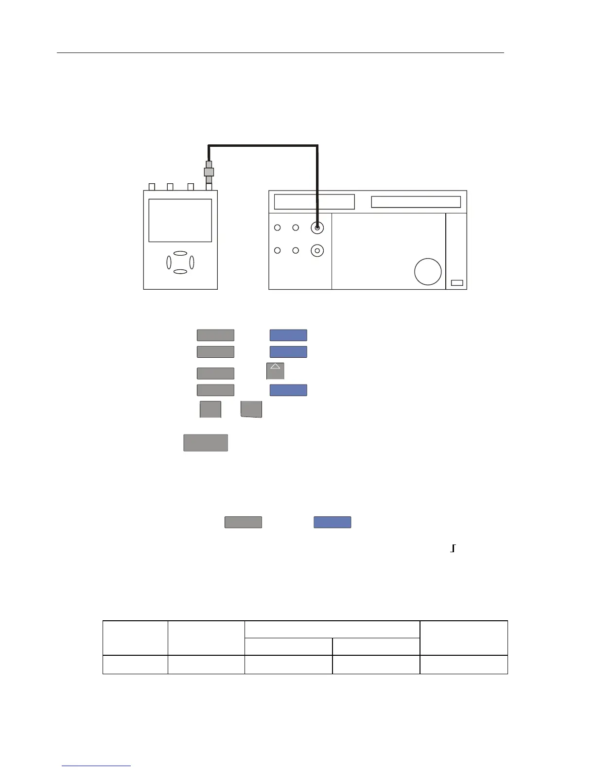
1. Connect the Test Tool to the 5500A as shown in Figure 4-10.
ADC
B
NORMAL
SCOPE
FLUKE 5500A CALIBRATOR
PM9091
PM9585 - 50 OHM
USE 50 OHM
TERMINATION
Figure 4-10. 5500A Scope Output to Test Tool Input D
2. Select the following Test Tool setup:
• Press
D
and use
F1
to turn Input D on.
• Press
C
and use
F1
to turn Input C off.
• Press
D
: using
MOVE
move the Input D trace zero to the center grid line.
• Press
TRIGGER
and use
F1
to select Input D as trigger source.
• Using
mV
RANGE
and
RANGE
change the sensitivity range to select manual sensitivity
ranging, and lock the Input D sensitivity range on 2 V/div.
3. Using
TIMEsns
select the time base indicated under the first column of Table 4-14.
4. Set the 5500A to source the leveled sine wave given in the first row of Table 4-14.
5. Adjust the 5500A output voltage until the displayed trace has the amplitude indicated
under the appropriate column of Table 4-14.
6. Verify that the signal is well triggered.
If it is not, press
TRIGGER
, then using
F3
enable the up/down arrow keys for
manual Trigger Level adjustment. Adjust the trigger level and verify that the signal
will be triggered now. The trigger level is indicated by the trigger icon (
).
7. Continue through the test points.
8. When you are finished, set the 5500A to Standby.
Table 4-14. Input B Trigger Sensitivity Test Points
UUT UUT 5500A SC... MODE levsin UUT
Model Time base Initial Input Voltage Frequency Trigger Amplitude
ALL 200 ns/div 100 mV pp 5 MHz 0.5 div