Calibration Adjustment
5.8 Probe Calibration 5
5-19
5.8 Probe Calibration
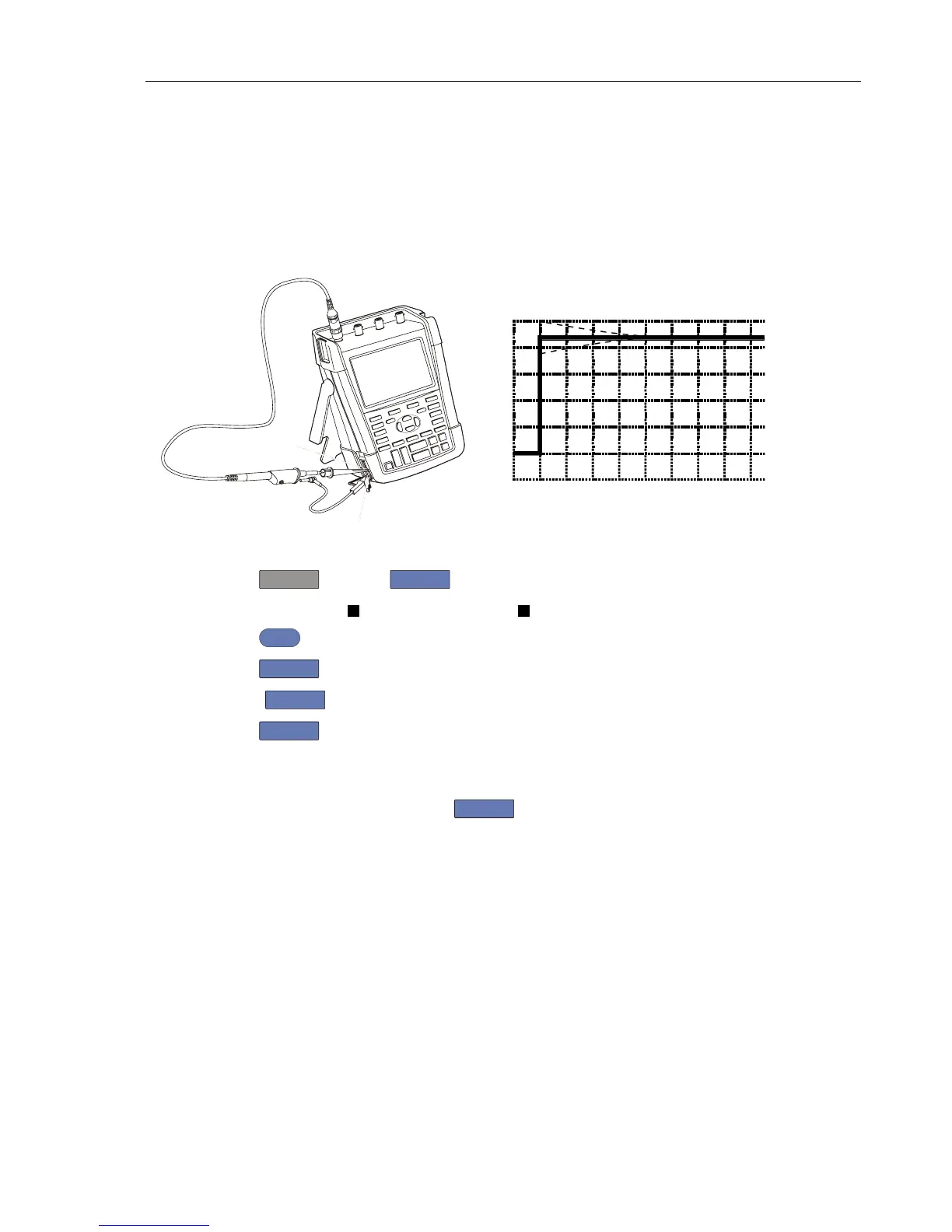
To meet full user specifications, you need to adjust the supplied red (R), blue (B), gray
(G) and green (V) VPS410 10:1 voltage probes for optimal response.
To adjust the VPS410 probes, do the following:
1. Connect the red probe from the red Input A BNC to the banana jacks. See figure 5-9
Probe Cal
Pr
, and then
F3
to open the Probe on A menu
3. Select Probe Type:
Voltage | Attenuation: 10:1 .
4. Press
ENTER
.
5. Press
F3
- PROBE A.
6.
Press
F1
- PROBE CAL and follow the instructions as displayed on screen.
7. Press
F4
to start the probe calibration. The first step is to manually adjust the
square wave response to a pure square wave (pulse top must be straight, refer to fig. 5-
10). The trimmer to be operated is located in the probe housing and can be reached by
rotating the centre part of the housing. For further information refer to the probe
instruction sheet. When done, press
F4
to start the DC calibration that is
performed automatically. The Probe Calibration is OK if all instructions displayed on
screen are finished succesfully.
Close the hole of the trimmer by rotating the centre part of the housing: this is
important for safe use of the probe at high input voltages.
8. Repeat the procedure for the blue VPS410-B probe, connected between the blue Input
B BNC and the probe cal terminals on the left side of the instrument.
9. Repeat the procedure for the gray VPS410-G probe, connected between the gray Input
C BNC and the probe cal terminals on the left side of the instrument.
10. Repeat the procedure for the green VPS410-V probe, connected between the green
Input D BNC and the probe cal terminals on the left side of the instrument.