Fluke 190-104/190-204
Service Information
5-12
Table 5-3. Input C LF-HF Gain Calibration Points
Cal step UUT input signal 5500A Setting
CL 0656 0.5 Vpp square wave, 1 kHz SCOPE edge, 0.5 Vpp, 1 kHz
CL 0470 0.5 Vpp square wave, 1 kHz SCOPE edge, 0.5 Vpp, 1 kHz
CL 0714 0.5 Vpp square wave, 1 kHz SCOPE edge, 0.5 Vpp, 1 kHz
CL 0478 0.5 Vpp square wave, 1 kHz SCOPE edge, 0.5 Vpp, 1 kHz
CL 0484 0.62 Vpp sine wave, 50 kHz SCOPE levsine, 0.62 Vpp, 50 kHz
CL 0485 0.62 Vpp sine wave
Fluke 190-204: 221 MHz
Fluke 190-104: 141 MHz
SCOPE levsine, 0.62 Vpp,
221 MHz
141 MHz
ADC
B
NORMAL
SCOPE
FLUKE 5500A CALIBRATOR
PM9091
PM9585 - 50 OHM
USE 50 OHM
TERMINATION
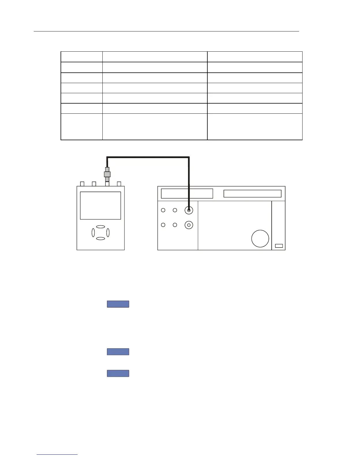
Figure 5-5. 5500A SCOPE Output to Test Tool Input C
5.6.5 Input D LF-HF Gain
Proceed as follows to do the Input D LF-HF Gain calibration:
1. Press
F2
to select the first calibration step in Table 5-4.
2. Connect the Test Tool to the 5500A as shown in Figure 5-6.
3. Set the 5500A SCOPE output to source the signal required for the first calibration
point in Table 5-4.
4. Set the 5500A in operate (OPR) or standby (STBY) as indicated.
5. Press
F3
to start the calibration.
6. Wait until the display shows calibration status
:READY .
7. Press
F2
to select the next calibration step, set the 5500A to the next
calibration point signal, and start the calibration.
Continue through all calibration points of Table 5-4.