Fluke 190-104/190-204
Service Information
4-18
200 ns/div levsine 1 MHz 300 mVpp -2 to +2
20 ns/div levsine 10 MHz 300 mVpp -3 to +3
4.6.8 Time Base Test
Proceed as follows to test the time base accuracy:
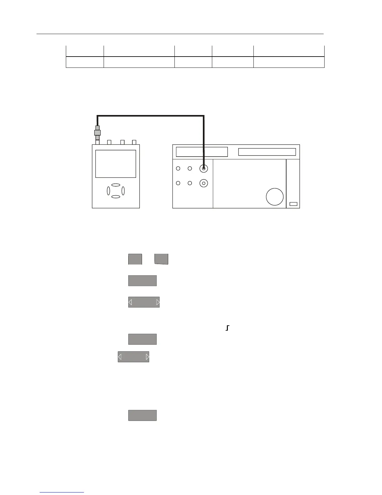
1. Connect the Test Tool to the 5500A as shown in Figure 4-6.
ADC
B
NORMAL
SCOPE
FLUKE 5500A CALIBRATOR
PM9091
PM9585 - 50 OHM
USE 50 OHM
TERMINATION
Figure 4-6. 5500A Scope Output to Test Tool Input A
2. Set the 5500A to source a 8 ms time marker (MODE marker).
3. Select the following Test Tool setup:
• Reset the Test Tool
• Using
mV
RANGE
and
RANGE
select manual vertical ranging, and set the Input A
sensitivity range to 500 mV/div (probe A factor is 1:1).
• Using
TIMEsns
change the time base to select manual time base ranging, and
lock the time base on 10 ms/div).
• Using
MOVE
move the trace to the left. After moving the trace 2 divisions,
the trigger delay time with respect to the first vertical grid line will be indicated
in the center of the display bottom.
Adjust the trigger delay time to 8.000 ms (
A →| 8.00 ms ).
• Using
TIMEsns
set the time base on 10 μs/div.
4. Using
MOVE
move the trace to the right until the indicated trigger delay is
7.990 ms.
5. Examine the rising edge of the time marker pulse at the height of the trigger level
indicator top. Verify that the rising edge is at the second grid line from the left. The
allowed deviation is ±3 pixels, see Figure 4-7.
6. Select the following Test Tool setup:
• Using
TIMEsns
change the time base to select manual time base ranging, and
lock the time base on 10 ms/div).