Fluke 190-104/190-204
Service Information
4-32
⇒ SECAM 310 (odd), for SECAM
⇒ NTSC 262 odd, for NTSC.
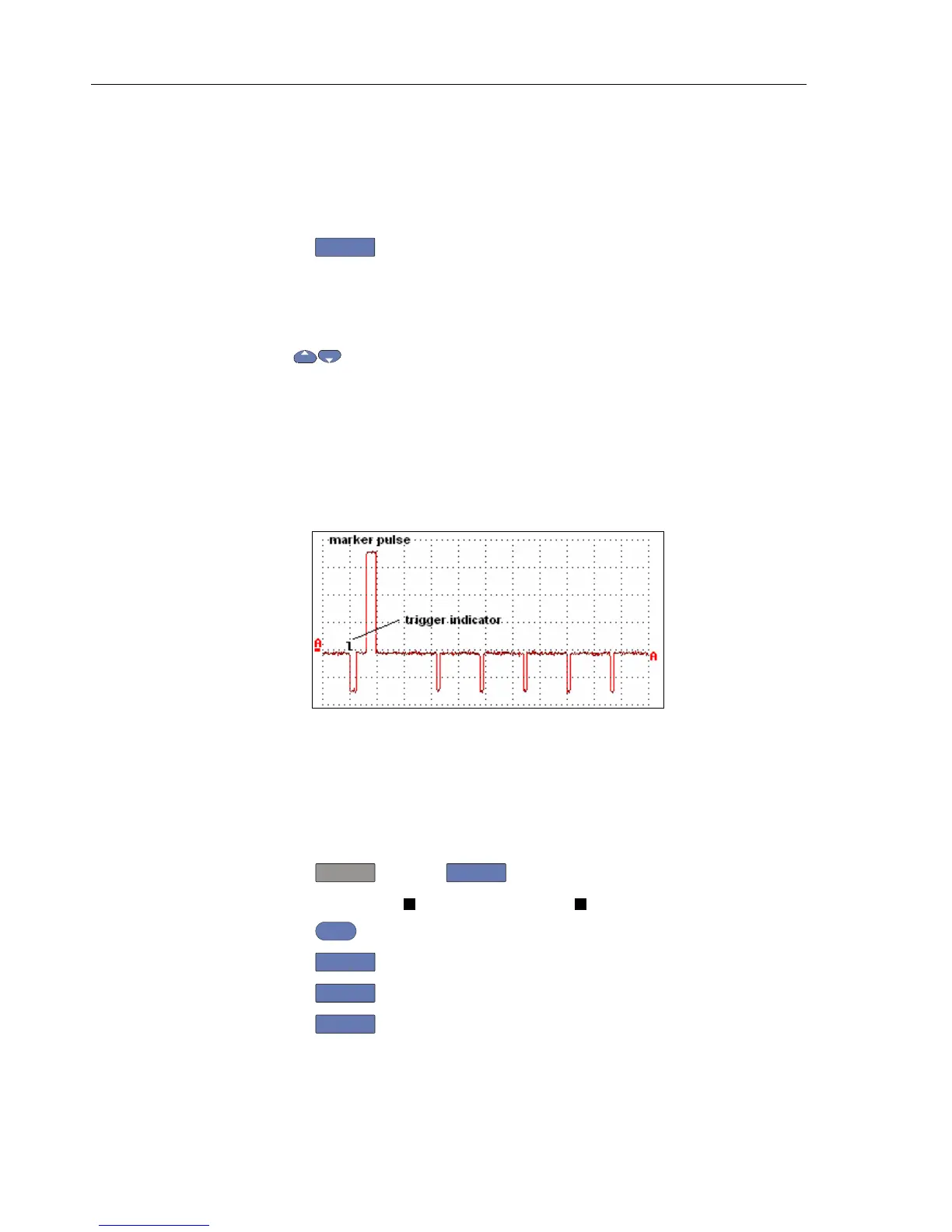
7. Observe the trace, and check to see if the Test Tool triggers on the negative pulse
before the marker.
8. Select the following Test Tool setup:
• Press
F4
to open the Trigger Options menu.
• Choose
VIDEO on A... , then from the shown opened menu choose
Polarity: NEGATIVE | PAL ( or NTSC or PALplus or SECAM )
9. Set the calibrator video trigger output signal to -100%
10. Using
select line number 310 (PAL, PALplus or SECAM) or 262 (NTSC)
11. Set the calibrator format and marker line number to :
⇒ PAL 310 (odd), for PAL and PALplus
⇒ SECAM 310 (odd), for SECAM
⇒ NTSC 262 odd, for NTSC.
12. Observe the trace, and check to see if the Test Tool triggers on the positive pulse
before the marker.
video-sc600.bmp
Figure 4-20. SC600 Marker Pulse
4.7 Probe Calibration Generator Test
To verify Connect a 10:1 probe as supplied with the Test Tool to input A (red probe).
Connect the probe tip and the probe’s ground lead with the probe cal terminals on the
lower left side of the Test Tool as shown in figure 4-21.
1. Press
, and then
F3
to open the Probe on A menu
2. Select Probe Type:
Voltage | Attenuation: 10:1 .
3. Press
ENTER
.
4. Press
F3
- PROBE A.
5. Press
F1
- PROBE CAL and follow the instructions as displayed on screen.
6. Press
F4
to start the probe calibration. The first step is to manually adjust
the square wave response to a pure square wave (pulse top must be straight). The
trimmer to be operated is located in the probe housing and can be reached by
 Loading...


