Performance Verification
4.6 Scope Input A, B, C, D Tests 4
4-31
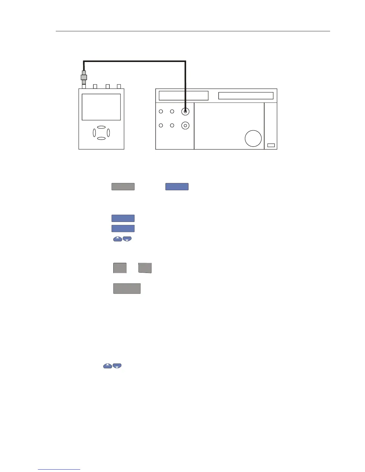
1. Connect the Test Tool to the calibrator as shown in Figure 4-19.
ADC
B
NORMAL
SCOPE
FLUKE 5500A CALIBRATOR
PM9091
PM9585 - 50 OHM
USE 50 OHM
TERMINATION
Figure 4-19. Test Tool Input A to TV Signal Generator
2. Select the following Test Tool setup:
• Reset the Test Tool
• Press
TRIGGER
, then press
F4
to open the Trigger Options menu.
• Choose
VIDEO on A... , then from the shown opened menu choose
Polarity: POSITIVE | PAL ( or NTSC or PALplus or SECAM )
• Press
F2
to select ALL LINES
• Press
F3
to enable the arrow keys for selecting the video line number.
• Using
select line number:
⇒ 622 for PAL, PALplus, or SECAM
⇒ 525 for NTSC.
• Using
mV
RANGE
and
RANGE
set the Input A sensitivity to 2 V/div (the actual probe
setting is 10:1).
• Using
TIMEsns
select the time base to 20 μs/div.
3. Set the calibrator to mode video with amplitude +100%. Set format and marker line
number to :
⇒ PAL 622 (even), for PAL and PALplus
⇒ SECAM 622 (even), for SECAM
⇒ NTSC 262 even, for NTSC.
4. Observe the trace, and check to see if the Test Tool triggers on the negative pulse
before the marker pulse (see Figure 4-20).
5. Using
select Test Tool line number:
⇒ 310 for PAL, PALplus or SECAM
⇒ 262 for NTSC
6. Set the calibrator format and marker line number to :
⇒ PAL 310 (odd), for PAL and PALplus
 Loading...


