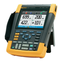
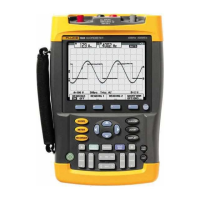
Fluke 190-104/190-204
Service Manual
3-4
3.3 Final Assembly Parts
See Table 3-1 and Figure 3-1, 3-2 and 3-3 for the Final Assembly parts.
Table 3-1. Final Assembly Parts and Kits
Part or Kit Ordering Code Consists of Following Parts Figure/Item nr
Case Set 3981815
Front case (Excl. lens/decal) 8-3 / 5
Dustseal long (2x) 8-3 / 3
Dustseal short (2x) 8-3 / 4
Case seal 8-3 / 13
Bottom case assy 8-1 / 3
Battery door 8-1 / 14
Quarter turn screw (2x) 8-1 / 15
Adhesive foam (for battery door) --
Standup bracket 8-1 / 14
Li-ion Battery Pack BP291 52 Wh, 10.8 V ---
Lens/decal 190-104 3981826
--- 8-3
Lens/decal 190-204 3981832
--- 8-3
LCD assy Flk-190-II 3981844
LCD module
LCD fixation foam
Flat cable
8-3 / 1
8-3 / 2
8-3 / 7
Topholster (Input
Cover)
3945328 --- 8-1 / 1
Sealing strip (flexible)
around inputs
3945319 --- 8-1 / 11
Mounting Material Set 3981859 Selftapping Screw 10 mm (2x, to fix
input cover)
8-1 / 2
Dowel (6x, to straps) 8-1 / 4
Steel Plate for Lock 8-1 / 5
Selftapping Screw 16.5 mm (4x, to
fix Rear Case)
8-1 / 6
Screw M3x6 (2x, to fix bottom
holster)
8-1 / 8
Selftapping Screw (6x, 10.5 mm to
fix Main PCA Module to Front Case)
8-3 / 12
Side Strap 3945370 Can be fixed on Left or Right side ---
Hang Strap 946769 Can be fixed op Top Side of
Instrument
---
Main PCA Module
(tested)
Only available for Fluke (authorized)
workshops. Requires dedicated tools
to configure.
8-1 / 12,13,
8-2, 8-3 / 8
Bottom Holster Set 3981867 Bottomholster assy 8-1 / 7
Cover for USB 8-1 / 9
Cover for DC adapter power 8-1 / 10
Connector Set 3981871 Probe signal pin (J8010)
Probe ground pin (J8011)
USB-A connector (J8007)
USB-B mini connector (J8003)

 Loading...
