Performance Verification
4.6 Scope Input A, B, C, D Tests 4
4-19
• Using
MOVE
move the trace to adjust the trigger delay time to 800.0 μs
(
A 800.0 μs).
• Using
TIMEsns
set the time base on 1 μs/div.
7. Set the 5500A to source a 0.8 ms time marker (MODE marker).
8. Using
MOVE
move the trace to the right until the indicated trigger delay is
799.0 μs.
9. Examine the rising edge of the time marker pulse at the vertical height of the trigger
level indicator top. Verify that the rising edge is at the second grid line from the left.
The allowed deviation is ±3 pixels, see Figure 4-7.
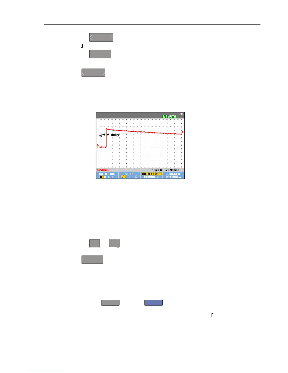
190c-tb1.bmp
Figure 4-7. Time Base Verification
4.6.9 Input A Trigger Sensitivity Test
Proceed as follows to test the Input A trigger sensitivity:
1. Connect the Test Tool to the 5500A as for the previous test (see Figure 4-6).
2. Select the following Test Tool setup:
• Reset the Test Tool
• Using
mV
RANGE
and
RANGE
change the sensitivity range to select manual sensitivity
ranging, and lock the Input A sensitivity range on 2 V/div.
3. Using
TIMEsns
select the time base indicated under the second column of
Table 4-8.
4. Set the 5500A to source the leveled sine wave for the appropriate Test Tool model.
5. Adjust the 5500A output voltage until the displayed trace has the trigger amplitude
indicated under the last column of Table 4-8.
6. Verify that the signal is well triggered.
If it is not, press
TRIGGER
, then using
F3
enable the up/down arrow keys for
manual Trigger Level adjustment. Adjust the trigger level and verify that the signal
will be triggered now. The trigger level is indicated by the trigger icon (
).
7. Continue through the test points.