Calibration Adjustment
5.6 Final Calibration 5
5-13
8. When you are finished, set the 5500A to Standby.
9. Continue at Section 5.6.6.
Table 5-4. Input D LF-HF Gain Calibration Points
Cal step UUT input signal 5500A Setting
CL 0675 0.5 Vpp square wave, 1 kHz SCOPE edge, 0.5 Vpp, 1 kHz
CL 0490 0.5 Vpp square wave, 1 kHz SCOPE edge, 0.5 Vpp, 1 kHz
CL 0734 0.5 Vpp square wave, 1 kHz SCOPE edge, 0.5 Vpp, 1 kHz
CL 0498 0.5 Vpp square wave, 1 kHz SCOPE edge, 0.5 Vpp, 1 kHz
CL 0486 0.62 Vpp sine wave, 50 kHz SCOPE levsine, 0.62 Vpp, 50 kHz
CL 0487 0.62 Vpp sine wave
Fluke 190-204: 221 MHz
Fluke 190-104: 141 MHz
SCOPE levsine, 0.62 Vpp,
221 MHz
141 MHz
ADC
B
NORMAL
SCOPE
FLUKE 5500A CALIBRATOR
PM9091
PM9585 - 50 OHM
USE 50 OHM
TERMINATION
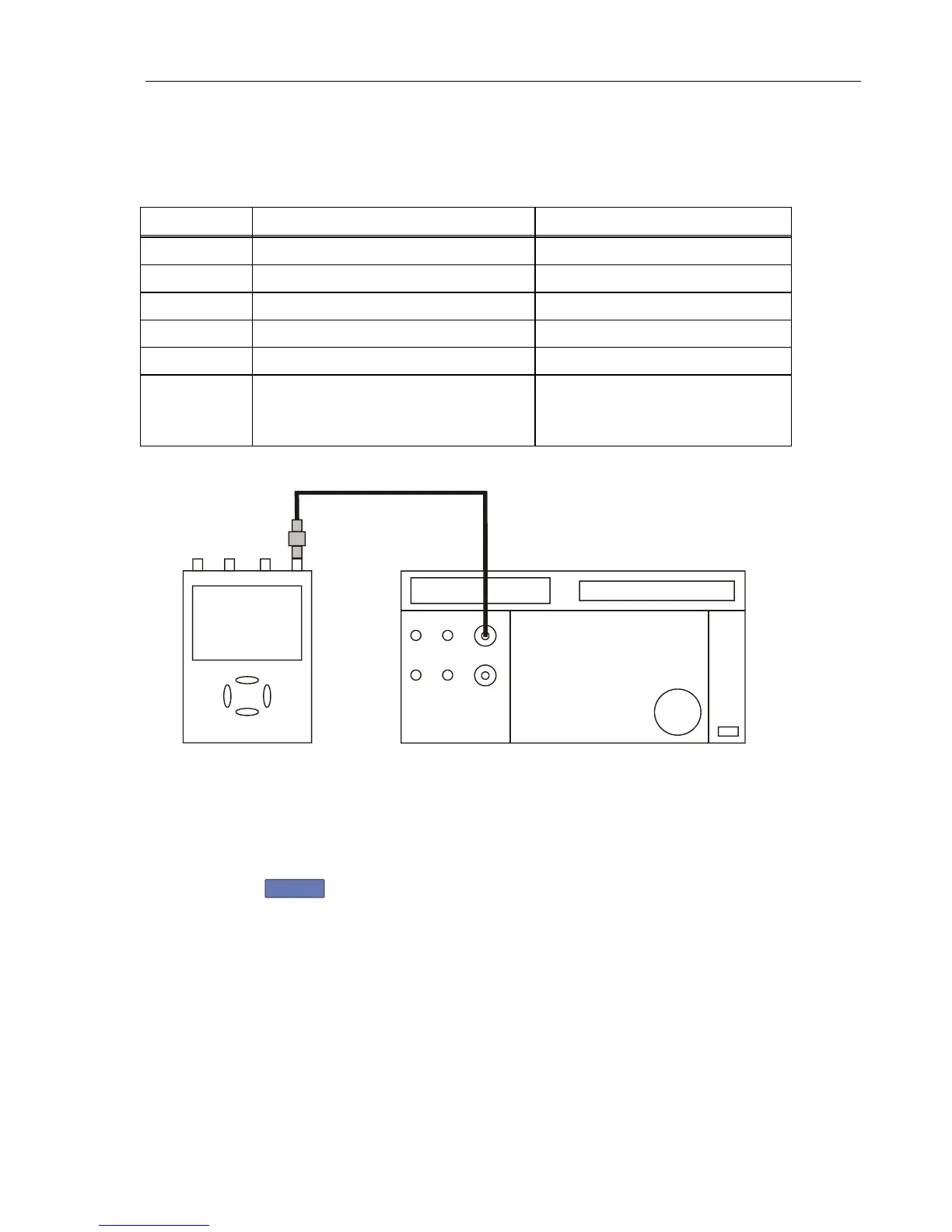
Figure 5-6. 5500A SCOPE Output to Test Tool Input D
5.6.6 Input ABCD LF-HF Gain
Proceed as follows to do the Input ABCD LF-HF Gain calibration.
1. Press
F2
to select the first calibration step in Table 5-5.
2. Connect the Test Tool to the 5500A as shown in Figure 5-7.