Fluke 190-104/190-204
Service Information
5-14
ADC
B
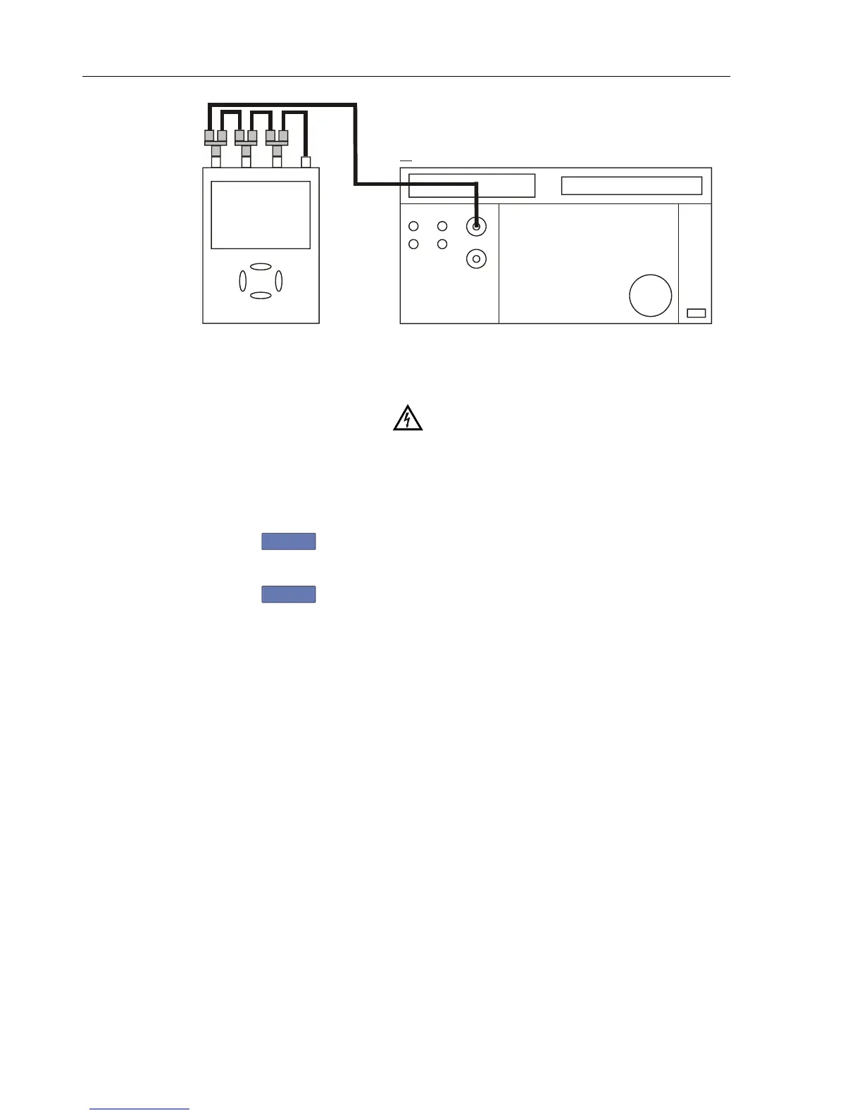
NORMAL SCOPE
FLUKE 5500A CALIBRATOR
PM9091
CONNECT TO CHANNEL A, B, C, D IN PARALLEL
50 OHM TERMINATIONNO
PM9093
PM9092
Figure 5-7. Test Tool Input ABCD to 5500A SCOPE Output
3. Set the 5500A to supply a 1 kHz square wave (SCOPE, MODE volt, SCOPE Z
1 MΩ), to the first calibration point in Table 5-5.
Warning
Dangerous voltages will be present on the calibration source
and connection cables during the following steps. Ensure that
the calibrator is in standby mode before making any connection
between the calibrator and the Test Tool.
4. Set the 5500A to operate (OPR).
5. Press
F3
to start the calibration.
6. Wait until the display shows calibration status
:READY.
7. Press
F2
to select the next calibration step, set the 5500A to the next
calibration point, and start the calibration. Continue through all calibration points of
Table 5-5.
8. Set the 5500A to Standby, and continue at Section 5.6.7.