Operation
Introduction
3
3-3
Introduction
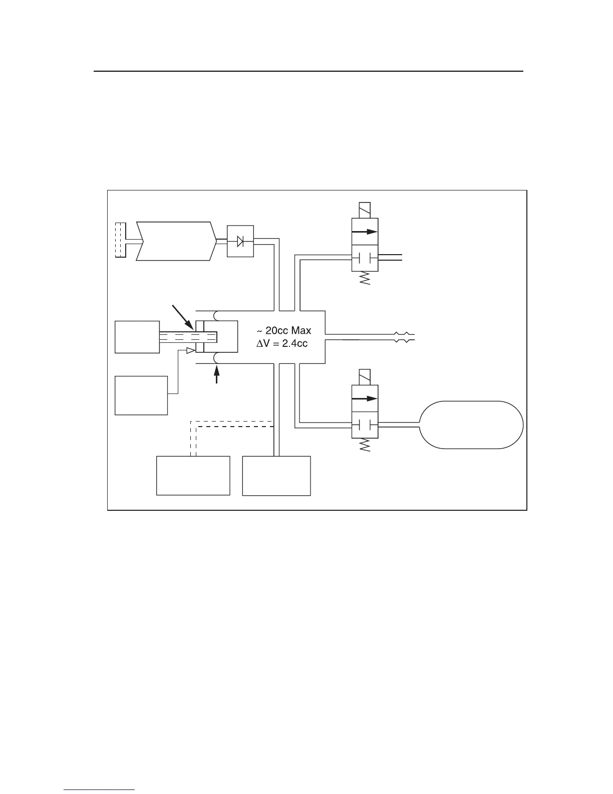
The Tester contains a microprocessor that reads and controls the front panel
keyboard, the display, serial port, printer port, a diaphragm pump, two solenoid
valves, a step motor, a position sensor, and a pressure transducer (Figure 3-1).
Filter
Step
Motor
Home
Position
Sensor
Lead Screw
and Piston
Option
Rolling
Seal
Ring Stud
N.C. Solenoid
Valve
Front Panel
Pressure Port
Vent/Zero Port
Internal Adult
Cuff Volume
290cc
12
Ring
Stud
N.C. Solenoid
Valve
12
Hi Accuracy
Pressure
Sensor
Standard
Pressure
Transducer
Check Valve
DC
Diaphragm
Pump
fas14.eps
Figure 3-1. Tester Pneumatic Block Diagram
The diaphragm pump is used as a pressure source for the relief valve, leak, and
pressure source tests. The diaphragm pump pulls air through a filter and forces it
through a check valve into the main manifold of the instrument. This main
manifold has an internal volume of approximately 20 cc and is directly connected
to the pressure port on the front panel. Pressure in the manifold is measured by a
pressure transducer and can be released by a solenoid-operated valve. The volume
of the main manifold can be increased by approximately 290 cc, to simulate an
adult pressure cuff, by opening a second solenoid valve.
A stepper motor and lead screw move a piston into the manifold to decrease the
manifold volume, thereby creating pressure pulses to simulate a human subject. A
seal around the piston is maintained by a rolling diaphragm seal. The size and