BP Pump 2
Operators Manual
3-4
shape of the pulses are controlled by the microprocessor driving the step motor.
The home position of the piston is detected by an optical interrupter. If the
optional high-accuracy pressure sensor is installed, it also measures the pressure in
the main manifold and is also controlled by the microprocessor.
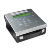
Configurations for Devices Under Test (DUT)
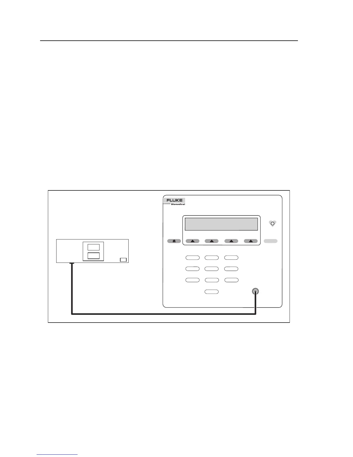
Connect the Tester to the NIBPM unit with the tubing and fittings (part number
2391882) supplied with the Tester in the desired configurations, as shown in
Figures 3-2 through 3-6.
Basically, configurations involve connecting the NIBPM unit to the Tester directly
or connecting the unit, a cuff, and the Tester, using a “T” connector. When
connected properly, the tubing forms a closed system with the components.
BP Pump 2
NON-INVASIVE BLOOD PRESSURE MONITOR ANALYZER
PRESSURE
LEAK
1
PRESSURE
RELIEF
TESTS AND SIMULATIONS
2
S
TA
TIC
PRESSURE
3
STANDARD BP
NEONATE
WRIST
PRESSURE PO
R
T
USER DEFINED
ARRHYTHMIAS
4
PATIENT
CONDITIONS
5
6
9
8
RESPIRITORY
ARTIFACT
7
0
ENT
120
93
80
80
NIBP Monitor
Single Hose: Internal Cuff
fas16.eps
Figure 3-2.Connecting Tester to Single-hose NIBP Monitor
(Int Cuff)