DSP-4000 Series
Users Manual
B-4
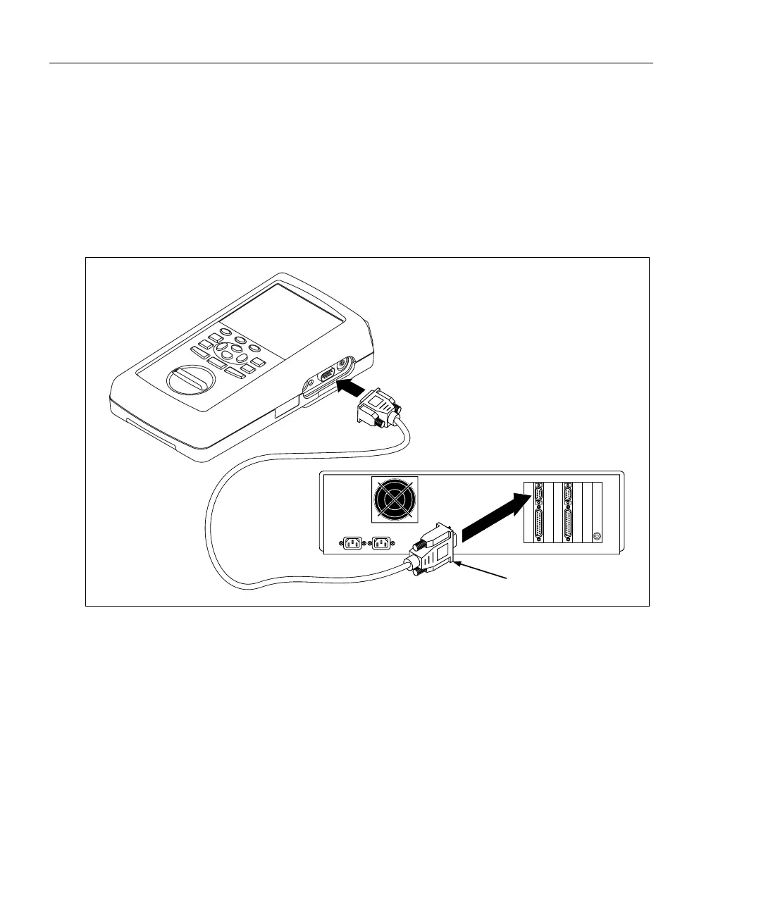
Connecting the Test Tool to a PC
To upload Autotest reports from a DSP-4000 or from a memory card installed in a
DSP-4100 test tool, connect the test tool to a PC using the 9-pin serial interface
cable provided with the test tool. Refer to Figure B-2. If your PC has a 25-pin
serial port, you can use a Fluke 25-pin adapter, Fluke P/N 929187.
To verify the pin assignments for a different 25-pin adapter or a different cable,
refer to the pin assignments for the serial interface cable given in “Specifications”
in Chapter 8.
12345678
PC Rear Panel (Typical)
Use the 9-pin to 25-pin
adapter if necessary.
oy41f.eps
Figure B-2. Connecting the Test Tool to a PC

 Loading...