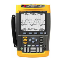
190 Series III
Users Manual
12
To make motor drive 3-phase current unbalance measurements:
1. Connect the current probes to the Inputs A, B and C.
2. Measure the current of each phase.
To make a motor shaft voltage measurement:
1. Connect the red VPS410-II voltage probe to the input A.
2. Connect the ground lead of the voltage probe to ground.
3. Connect a brush on top of the voltage probe.
4. Place the probe in probe holder.
5. Use the extension rod and magnetic base to keep the probe in a fixed position and the brush
in good contact with the motor shaft.
Probe Type Setup
To obtain correct measurement results the test tool probe type settings must correspond to the
connected probe types.
To select the input A probe setting:
1. Press A to show the INPUT A key labels.
2. Press 3 to open the PROBE ON A menu.
3. Use the cursor and E to select the probe type Voltage, Current, or Temp.
a. Voltage: select the voltage probe attenuation factor.
b. Current and Temp: select the current probe or temperature probe sensitivity.
1.888.610.7664 sales@GlobalTestSupply.com
Fluke-Direct.com

 Loading...


