13
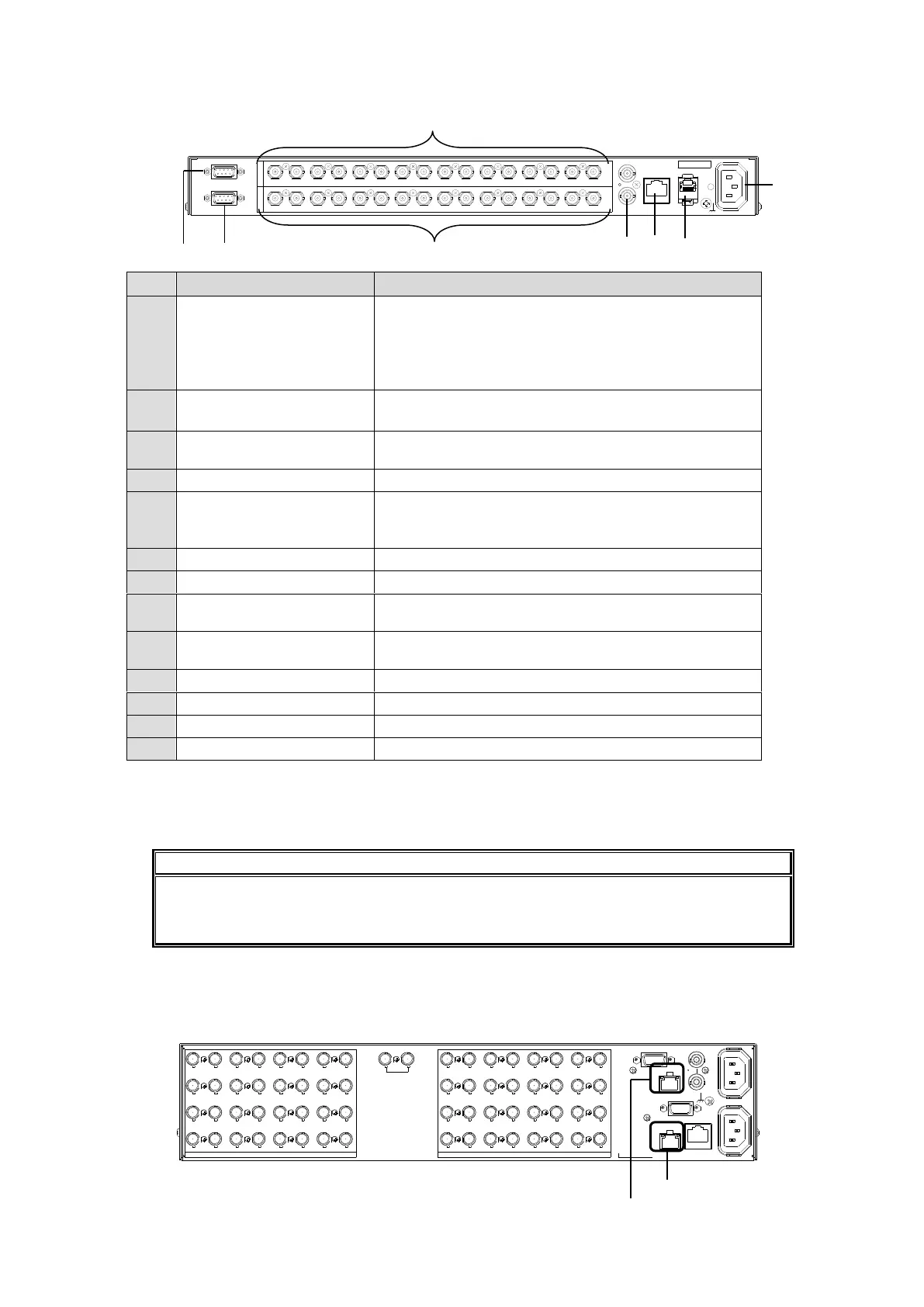
MFR-1616A
MFR-LAN *1
(1) MFR-LAN (CPU1) *1
(2) MFR-LAN (CPU2) *1
Ethernet ports for connection to MFR Remote Control
Units and MFR-GPI.
An Ethernet port (10/100BASE-T RJ-45)
(1) for the MAIN CARD
(2) for the MFR-SRCPU (option)
Used to connect to a PC or other external unit.
An Ethernet port (10/100BASE-TX RJ-45)
Used to control via a serial interface (RS-232C/RS-422
selectable)
Used to input a reference signal (BB or Tri-level sync
signal)
(looping, or 75 ohm terminated)
Used to input digital component video signals
Used to input digital component video signals
Used to connect Power Supply Unit 1 to an AC power
source
Used to connect Power Supply Unit 2 (optional) to an
AC power source.
Used to output AES/EBU audio signals.
Used to input AES/EBU audio signals.
Used to control via RS-232C.
*1 The MFR-LAN/MFR-LAN(CPU1, 2) connector may be labeled as TO RU, and the PC-LAN
connector as TO PC on units shipped before Sep. 16, 2011.
*2 The SERIAL connector is set to RS-232C as factory default. Consult your FOR-A reseller if
you wish to change the setting.
The MFR-LAN/MFR-LAN (CPU1, 2) ports must be connected to a LAN to enable
operation. The LAN connections for MFR Series devices must be separated from the
network segment of other devices.
When Installing MFR-SRCPU
Installing the MFR-SRCPU card enables MFR-1616R / 3216 / 3216RPS / 3232 / 3232RPS
units to have redundant CPU cards and Ethernet ports, which can be used for remote control
panel connection.
AC100-240V 50/60Hz IN 2 AC100-240V 50/60Hz IN 1
SERIAL
ALARM
TO RS
SDI OUT
1
2
3
4
5
6
7
8
9
10
11
12
13
14
15
16
17
18
19
20
21
22
23
24
25
26
27
28
29
30
31
32
REF IN
SDI IN
1
2
3
4
5
6
7
8
9
10
11
12
13
14
15
16
17
18
19
20
21
22
23
24
25
26
27
28
29
30
31
32
M FR -LAN (C PU1 )
M FR -LAN (C PU2 )
PC-LAN
A
C
1
0
0
-
2
4
0
V
5
0
/6
0
H
z
IN
SER. NO.
MFR-LAN
PC-LAN
REF IN
ALARM
RS-232C
A
E
S
I
N
A
E
S
O
U
T
1 2 3 4
1 2 3 4 5 6 7
5 6 7 8 9 10 11 12 13 14 15
8 9 10 11 12 13 14 15 16
16

 Loading...