EasyManuals Logo

FOR-A MFR Series Operation Manuals

FOR-A MFR Series
59 pages
To Next Page IconTo Next Page
To Previous Page IconTo Previous Page
Page #14 background imageLoading...
Page #14 background image
14
IMPORTANT
When using the MFR-SRCPU, be sure to connect both MFR-LAN(CPU1) and
MFR-LAN(CPU2) connectors to a LAN interface.
See the separate MFR SERIES Web-based Control Operation Manual for more
information on MFR-SRCPU.
2-1-3. Interfaces
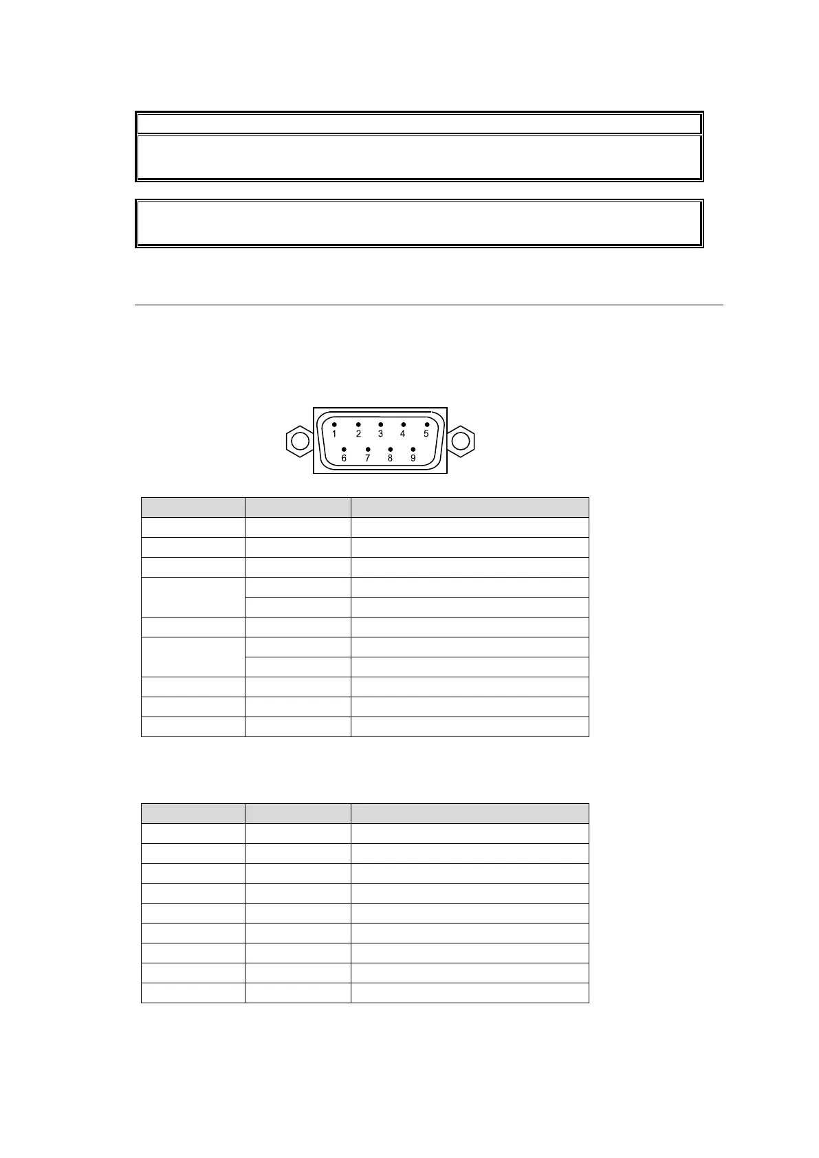
SERIAL Connector (9-pin D-sub, male)
RS-232C or 422 interface is selectable. The factory default setting is RS-232C. Consult your
FOR-A reseller if you wish to change the setting.
RS-232C Connector Pin Assignments
Pin No.
Signal Name
Description
1
NC
Not used
2
RxD
Received Data
3
TxD
Transmitted Data
4
DTR
Data Terminal Ready
NC
Not used (MFR-1616A only)
5
SG
Signal Ground
6
DSR
Data Set Ready
NC
Not used(MFR-1616A only)
7
RTS
Request To Send
8
CTS
Clear To Send
9
NC
Not used
* The maximum cable length is 10 m.
* DTR/DSR and RTS/CTS are internally connected respectively.
RS-422 connector pin assignment (9-pin, D-sub male)
Pin No.
Signal Name
Description
1
FG
Frame Ground
2
T-
Transmit data (-)
3
R+
Receive data (+)
4
SG
Signal Ground
5
NC
Not used
6
SG
Signal Ground
7
T+
Transmit data (+)
8
R-
Receive data (-)
9
FG
Frame Ground
* The maximum cable length is 100 m.
9-pin D-sub, male

Other manuals for FOR-A MFR Series

Questions and Answers:

Question and Answer IconNeed help?

Do you have a question about the FOR-A MFR Series and is the answer not in the manual?

FOR-A MFR Series Specifications

General IconGeneral
BrandFOR-A
ModelMFR Series
CategorySwitch
LanguageEnglish

Related product manuals